MAX5500/MAX5501
Low-Power, Quad, 12-Bit
Voltage-Output DACs with Serial Interface
10 ______________________________________________________________________________________
CS
SCLK
DIN
DOUT
(MODE 1)
MSB FROM
PREVIOUS WRITE
MSB FROM
PREVIOUS WRITE
COMMAND
EXECUTED
9
8
16
1
A0
A1 D0
C1
C0
D11
D10
D9
D6
D5
D4
D3
D2
D1
D8
D7
DOUT
(MODE 0)
A0
A1 D0 A1
C1
C0
D11
D10
D9
D6
D5
D4
D3
D2
D1
D8
D7
A0
A1 D0 A1
C1
C0
D11
D10
D9
D6
D5
D4
D3
D2
D1
D8
D7
DATA PACKET (N)
DATA PACKET (N-1)
DATA PACKET (N)
DATA PACKET (N-1)
DATA PACKET (N)
Figure 5. Serial-Interface Timing Diagram
SCLK
DIN
DOUT
t
CSO
t
CSS
t
CL
t
CH
t
CP
t
DO1
t
CSW
t
CS1
t
DO2
t
CSH
t
DS
t
DH
CS
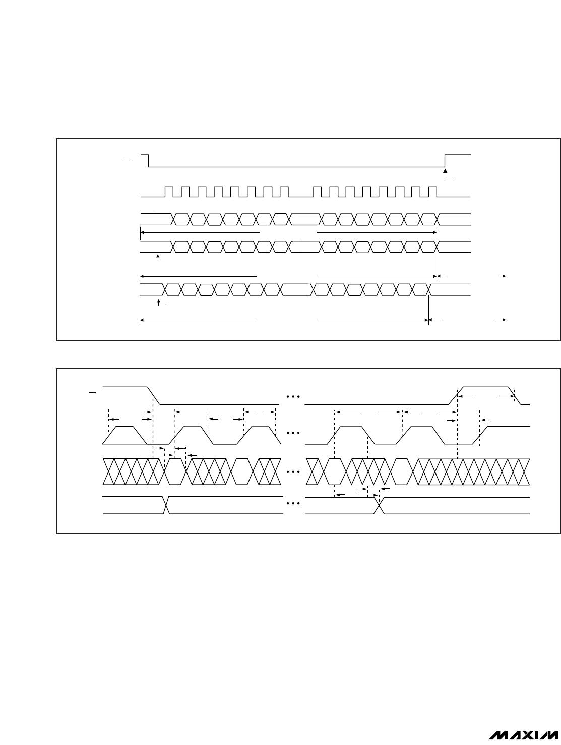
Figure 6. Detailed Serial-Interface Timing Diagram
Power
-
Down Lockout
(PDL)
Drive power-down lockout, PDL, low to disable software
shutdown. When in shutdown, transitioning PDL from
high to low wakes up the device with the output set to
the state prior to shutdown. Use PDL to asynchronously
wake up the device.
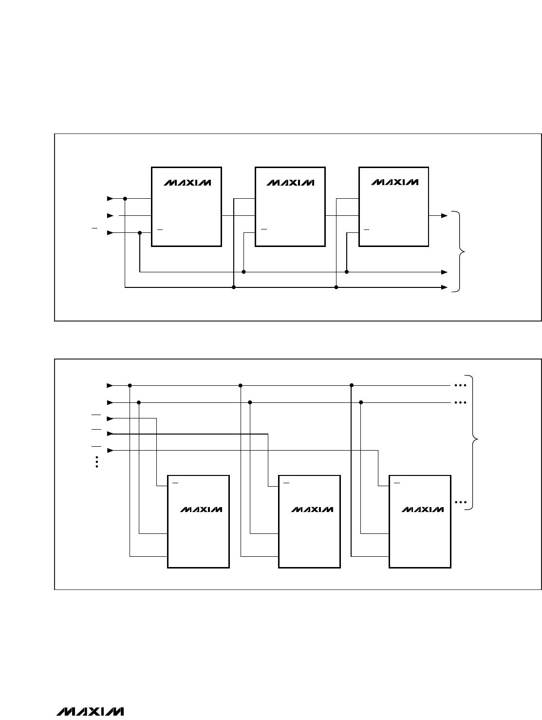
Daisy Chaining Devices
The MAX5500/MAX5501 can be daisy chained by con-
necting DOUT of one device to DIN of another device
(Figure 7).
Each DOUT output of the MAX5500/MAX5501 includes
an internal active pullup. The sink/source capability of
DOUT determines the time required to discharge/charge
a capacitive load. See the serial-data-out V
OH
and V
OL
specifications in the
Electrical Characteristics.
Figure 8 shows an alternate method of connecting sev-
eral MAX5500/MAX5501 devices. In this configuration,
the data bus is common to all devices. Data is not shift-
ed through a daisy chain. More I/O lines are required in
this configuration because a dedicated chip-select
input (CS) is required for each IC.
MAX5500/MAX5501
Low-Power, Quad, 12-Bit
Voltage-Output DACs with Serial Interface
______________________________________________________________________________________ 11
DIN
CS
TO OTHER
SERIAL DEVICES
MAX5500
MAX5501
SCLK
DIN
CS
DOUT
MAX5500
MAX5501
SCLK
DIN
CS
DOUT
MAX5500
MAX5501
SCLK
DIN
CS
DOUT
SCLK
Figure 7. Daisy Chaining MAX5500/MAX5501
TO OTHER
SERIAL DEVICES
MAX5500
MAX5501
DIN
SCLK
CS
MAX5500
MAX5501
DIN
SCLK
CS
MAX5500
MAX5501
DIN
SCLK
CS
DIN
SCLK
CS1
CS2
CS3
Figure 8. Multiple MAX5500/MAX5501 Devices Sharing a Common DIN Line
MAX5500/MAX5501
Low-Power, Quad, 12-Bit
Voltage-Output DACs with Serial Interface
12 ______________________________________________________________________________________
DAC CONTENTS
ANALOG OUTPUT
MSB LSB
4095
1111 1111 1111 +V
REF
( ——— )
4096
2049
1000 0000 0001 +V
REF
( ——— )
4096
2048 +V
REF
1000 0000 0000 +V
REF
( ——— )= ————
4096 2
2047
0111 1111 1111 +V
REF
( ——— )
4096
1
0000 0000 0001 +V
REF
( ——— )
4096
0000 0000 0000 0V
Table 2. Unipolar Code Table
DAC CONTENTS
ANALOG OUTPUT
MSB LSB
2047
1111 1111 1111 +V
REF
( ——— )
2048
1
1000 0000 0001 +V
REF
( ——— )
2048
1000 0000 0000 0V
1
0111 1111 1111 -V
REF
( ——— )
2048
2047
0000 0000 0001 -V
REF
(
——— )
2048
2048
0000 0000 0000 -V
REF
(
——— )= -V
REF
2048
Table 3. Bipolar Code Table
Note: 1 LSB = (V
REF
) (
4096
)
1
MAX5500
MAX5501
DAC A
DAC B
DAC C
DAC D
OUTA
FBA
FBB
FBC
FBD
OUTB
OUTC
OUTD
DGNDAGND
REFAB
REFCD
REFERENCE INPUTS
+5V
V
DD
Figure 9. Unipolar Output Circuit
MAX5500
MAX5501
DAC A
DAC B
DAC C
DAC D
V
REFAB
= V
REFCD
= 2.5V
OUTA
10k
10k
10k
10k
10k
10k
10k
10k
OUTB
OUTC
OUTD
DGNDAGND
REFAB
REFCD
REFERENCE INPUTS
+5V
V
DD
FBA
FBB
FBC
FBD
Figure 10. Unipolar Rail-to-Rail Output Circuit
Applications Information
Unipolar Output
For a unipolar output, the output voltages and the refer-
ence inputs are of the same polarity. Figure 9 shows
the MAX5500/MAX5501 unipolar output circuit, which is
also the typical operating circuit. Table 2 lists the unipo-
lar output codes.
See Figure 10 for rail-to-rail outputs. Figure 10 shows
the MAX5500/MAX5501 with the output amplifiers con-
figured with a closed-loop gain of +2 to provide 0 to 5V
full-scale range with a 2.5V external reference voltage.
Bipolar Output
Figure 11 shows the MAX5500/MAX5501 configured for
bipolar operation.
V
OUT
= V
REF
[(2NB/4096) - 1]
where NB is the numeric value of the DAC’s binary
input code. Table 3 shows digital codes (offset binary)
and corresponding output voltages for the circuit of
Figure 11.

MAX5500AGAP+

Mfr. #:
Manufacturer:
Maxim Integrated
Description:
Digital to Analog Converters - DAC 12-Bit 4Ch Precision DAC
Lifecycle:
New from this manufacturer.
Delivery:
DHL FedEx Ups TNT EMS
Payment:
T/T Paypal Visa MoneyGram Western Union