9
FN6514.2
October 30, 2007
All devices in this family feature low power shutdown,
thermal overload protection and click/pop suppression. The
click and pop circuitry prohibits switching between input
channels until the audio input signals are at there lowest
point which eliminates audible transients in the speakers
when changing the audio input sources. The click/pop
circuitry also keeps speaker transients to an inaudibile level
when entering and leaving shutdown.
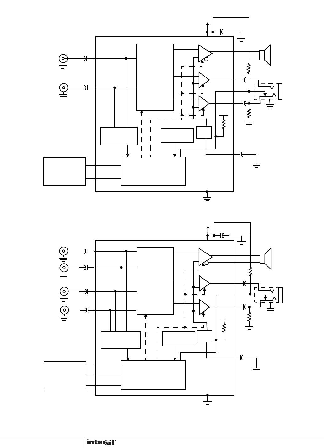
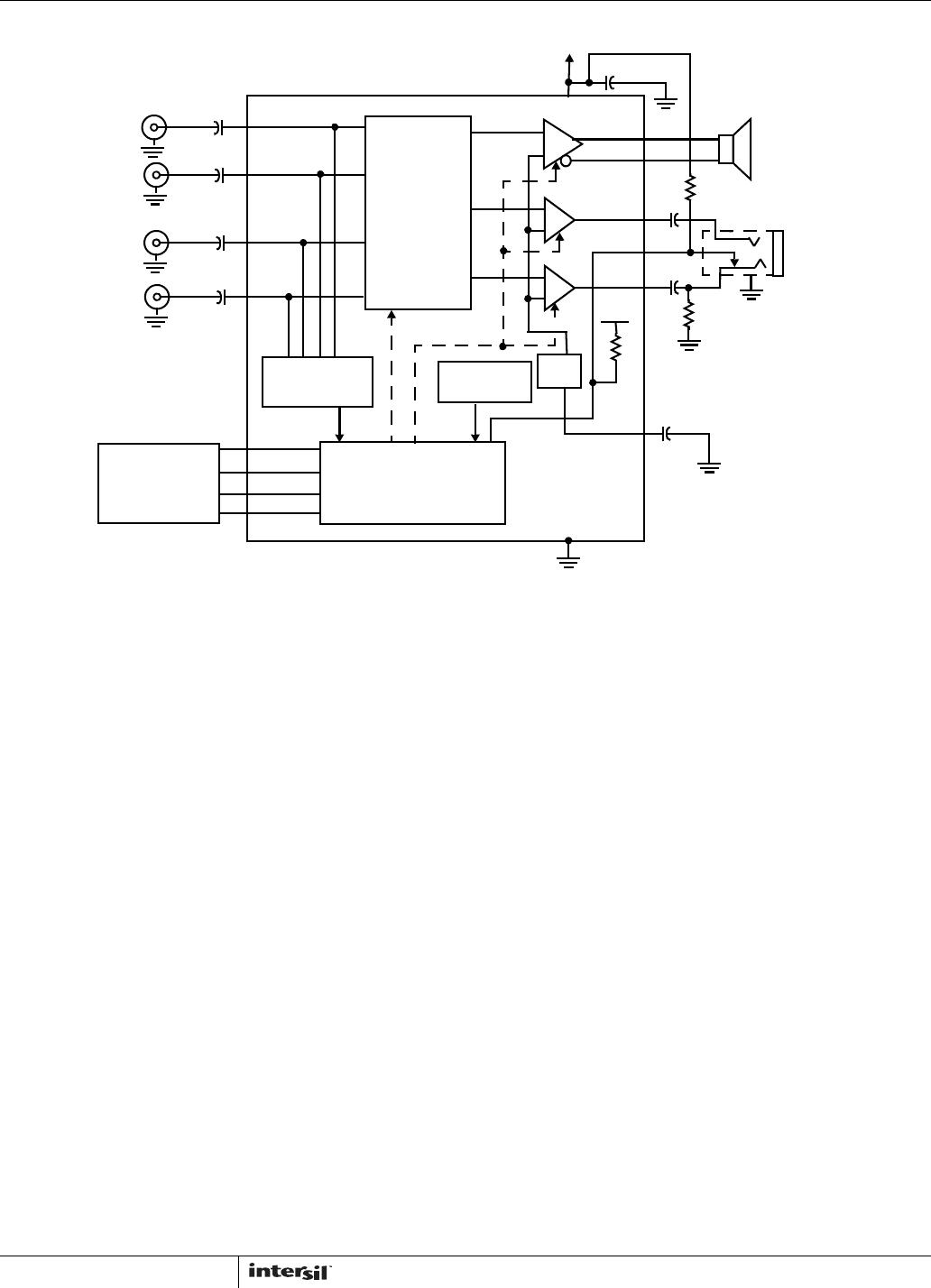
“Typical Application Circuits and Block Diagrams” for each
device in the family are provided on page 7 and page 8.
Truth tables for each device are provided on page 3.
DC Bias Voltage
The ISL54003, ISL54005, and ISL54006 have internal DC
bias circuitry, which DC offsets the incoming audio signal at
V
DD
/2. When using a 5V supply, the DC offset will be 2.5V.
When using a 3.6V supply, the DC offset will be 1.8V.
Since the signal gets biased internally at V
DD
/2 the audio
signals need to be AC coupled to the inputs of the device.
The value of the AC coupling capacitor depends on the low
frequency range required for the application. A capacitor of
0.22µF will pass a signal as low as 7.2Hz. The formula
required to calculated the capacitor value is shown in
Equation 1:
The 100k is the impedance looking into the input of the
ISL54003, ISL54004, ISL54006 devices.
BTL Speaker Amplifier
The ISL54003, ISL54005, and ISL54006 contain one
bridge-tied load (BTL) amplifier designed to drive an 8
speaker load differentially. The output to the BTL amplifier
are SPK+ and SPK-. The speaker load gets connected
across these terminals.
A single BTL driver consists of an inverting and non-inverting
power op amps. The AC signal out of each op amp are equal
in magnitude but 180° out-of-phase, so the AC signal at
SPK+ and SPK- have the same amplitude but are 180°
out-of-phase.
Driving the load differentially using a BTL configuration
doubles the output voltage across the speaker load and
quadruples the power to the load. In effect you get a gain of
two due to this configuration at the load as compared to
driving the load with a single-ended amplifier with its load
connected between a single amplifier’s output and ground.
The outputs of the BTL are biased at V
DD
/2. When the load
gets connected across the + and - terminal of the BTL the
mid supply DC bias voltage at each output gets cancelled
out eliminating the need for large bulky output coupling
capacitors.
Headphone (Single-Ended) Amplifiers
The ISL54003, ISL54005, and ISL54006 contains two
single-ended (SE) headphone amplifiers for driving the left
and right channels of a 32 or 16 headphone speaker.
One SE amplifier drives the right speaker of the headphone
and other SE amplifier drives the left speaker of the
headphone. The speaker load gets connected between the
output of the amplifier and ground.
The audio signal at the output of each SE driver is biased at
V
DD
/2 and unlike the BTL driver that cancels this offset due
to its differential connection, a capacitor is required at the
output of each SE drivers to remove this DC voltage from the
headphone load.
This coupling capacitor along with the resistance of the
speaker load creates a high pass filter that sets the
amplifier’s lower bandpass frequency limit. The value of this
AC coupling capacitor depends on the low frequency range
required by the application. The formula required to calculate
the capacitor value is shown in Equation 2:
For an application driving a 32 headphone with a lower
frequency requirement of 150Hz, the required capacitor
value would be determined by using Equation 3:
Use the closest standard value.
Headphone Sense Function
With a logic “1” at the HP control pin while the HO control pin
is low will activate the headphone drivers and disable the
BTL driver.
The “Typical Application Circuits and Block Diagrams” on
page 7 and page 8 show the implementation of the
headphone control function using a common headphone
jack.
The HP pin gets connected to the mechanical wiper blade of
the headphone jack. Two external resistors are required for
proper operation. A 100k pull-up resistor from the HP pin to
V
DD
and a 10k pull-down resistor from the jack’s audio
signal pin to ground of the jack signal pin to which the wiper
is connected. See the block diagrams on page 7 and page 8.
When no headphone plug is inserted into the jack, the
voltage at the HP pin gets set at a low voltage level due to
the 10k resistor and 100k resistor divider network
connection to V
DD
.
When a headphone is inserted into the jack, the 10k
resistor gets disconnected from the HP control pin and the
HP pin gets pulled up to V
DD
. Since the HP pin is now high,
the headphone drivers are activated.
(EQ. 1)
C 1 6.28 f 100k
(EQ. 2)
C 1 6.28 f Rspeaker
(EQ. 3)
C 1 6.28 150 32 33F=
ISL54003, ISL54005, ISL54006