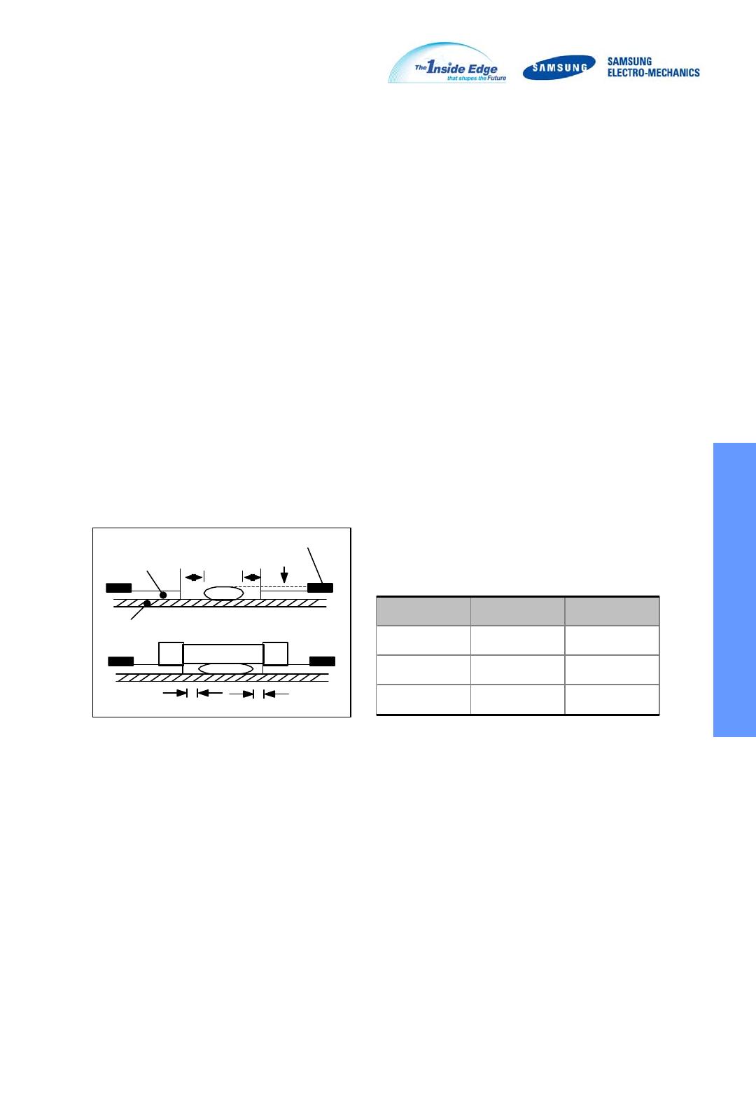
APPLICATION MANUAL
General Capacitors
ELECTRICAL CHARACTERISTICS
CAPACITANCE CHANGE - AGING
IMPEDANCE - FREQUENCY CHARACTERISTICS
CAPACITANCE - DC VOLTAGE CHARACTERISTICS
C0G
0.01
0.1
1
10
100
1.E+06 1.E+07 1.E+08 1.E+09 1.E+10
Ohm
1MHz 10MHz 100MHz 1GHz 10GHz
1000pF
100pF
10pF
X7R/X5R/Y5V
0.01
0.1
1
10
100
1.E+06 1.E+07 1.E+08 1.E+09
Ohm
0.1
0.01
0.001
1MHz 10MHz 100MHz 1GHz
CAPACITANCE - TEMPERATURE CHARACTERISTICS
40
20
-20
-4 0
-60
-80
-20-4 0-60
25 40 60 80 10 0 120
X7R
X5R
Y5V
% C
40
20
-20
-4 0
-60
-80
-20-4 0-60
25 40 60 80 10 0 120
X7R
X5R
Y5V
% C
20
10 20 30 40 50
X7R 50V
X7R 16V
Y5V
C %
Vdc
COG
X5R 50V
10
0
-10
-20
-30
-40
-50
-60
-70
-80
-90
-100
20
10 20 30 40 50
X7R 50V
X7R 16V
Y5V
C %
Vdc
COG
X5R 50V
10
0
-10
-20
-30
-40
-50
-60
-70
-80
-90
-100
1 10 1 00 1000 10000
Time(hr)
Δ
C/C [%]
Y5V
C0G
X7R/X5R
5
10
15
1 10 1 00 1000 10000
Time(hr)
Δ
C/C [%]
Y5V
C0G
X7R/X5R
5
10
15
8
6
4
2
-4
-6
-8
-10
-2
-55 -40 -20 25 40 60 80 100 125
S2L
U2J
COG
% C
Temp.(
o
C)
o
8
6
4
2
-4
-6
-8
-10
-2
-55 -40 -20 25 40 60 80 100 125
S2L
U2J
COG
% C
Temp.(
o
C)
o
W b
a
Solder
Land
Solder Resist
2/3W < b < W
T
Solder Resist
2/3T < a < T
General Capacitors
STORAGE CONDITION
Storage Environment
The electrical characteristics of MLCCs were degraded by the environment of high temperature or
humidity. Therefore, the MLCCs shall be stored in the ambient temperature and the relative humidity
of less than 40 and 70%, respectively.
Guaranteed storage period is within 6 months from the outgoing date of delivery.
Corrosive Gases
Since the solderability of the end termination in MLCC was degraded by a chemical atmosphere
such as chlorine, acid or sulfide gases, MLCCs must be avoid from these gases.
Temperature Fluctuations
Since dew condensation may occur by the differences in temperature when the MLCCs are taken
out of storage, it is important to maintain the temperature-controlled environment
.
DESIGN OF LAND PATTERN
When designing printed circuit boards, the shape and size of the lands must allow for the proper
amount of solder on the capacitor.
The amount of solder at the end terminations has a direct effect on the crack.
The crack in MLCC will be easily occurred by the tensile stress which was due to too much amount
of solder. In contrast, if too little solder is applied, the termination strength will be insufficiently.
Use the following illustrations as guidelines for proper land design.
Recommendation of Land Shape and Size.
ADHESIVES
When flow soldering the MLCCs, apply the adhesive in accordance with the following conditions.
Requirements for Adhesives
They must have enough adhesion, so that, the chips will not fall off or move during the handling of the
circuit board.
They must maintain their adhesive strength when exposed to soldering temperature.
They should not spread or run when applied to the circuit board.
They should harden quickly. They should not corrode the circuit board or chip material.
They should be a good insulator. They should be non-toxic, and not produce harmful gases, nor be
harmful when touched.
Application Method
It is important to use the proper amount of adhesive. Too little and much adhesive will cause poor
adhesion and overflow into the land, respectively.
Adhesive hardening Characteristics
To prevent oxidation of the terminations, the adhesive must harden at 160 or less, within 2 minutes
or less
.
MOUNTING
Mounting Head Pressure
Excessive pressure will cause crack to MLCCs. The pressure of nozzle will be 300g maximum during
mounting.
Solder Resist
Land
PCB
aa
b
c
c
Type 21 31
a
0.2 min 0.2 min
b
70~100
70~100
c
>0 >0
unit : mm
General Capacitors

CL10B104KB8NNNC

Mfr. #:
Manufacturer:
Description:
CAP CER 0.1UF 50V X7R 0603
Lifecycle:
New from this manufacturer.
Delivery:
DHL FedEx Ups TNT EMS
Payment:
T/T Paypal Visa MoneyGram Western Union