General Capacitors
NO
ITEM PERFORMANCE TEST CONDITION
7
Temperature
Characteristics
of Capacitance
Class
Capacitance shall be measured by the steps
shown in the following table.
(1) Class
Temperature Coefficient shall be calculated from
the formula as below.
C1
×
T
×10
6
[ppm/ ]
C2 - C1
Temp, Coefficient =
C1; Capacitance at step 3
C2: Capacitance at 85
T: 60
(=85
-25
)
(2) CLASS
Capacitance Change shall be calculated from the
formula as below.
×100(%)
C2 - C1
C1
C=
C1; Capacitance at step 3
C2: Capacitance at step 2 or 4
Class
8
Adhesive Strength
of Termination
No Indication Of Peeling Shall Occur On The
Terminal Electrode.
Apply 500g.f * Pressure for 10
±
1sec.
* 200g.f for 0201 case size.
9
Bending
Strength
Apperance No mechanical damage shall occur.
Bending limit ; 1mm
Test speed ; 1.0mm/SEC.
Keep the test board at the limit point in 5 sec.,
Then measure capacitance.
Capacitance
Characteristics Capacitance Change
Class I
Within
±
5% or
±
0.
5 pF whichever is
larger
Class II
A(X5R)/
B(X7R)/
X(X6S)
Within
±
12.5%
F(Y5V) Within
±
30%
Characteristics
Capacitance Change
with No Bias
A(X5R)/
B(X7R)
±
15%
X(X6S)
±
22%
F(Y5V) +22% ~ -82%
500g.f
Characteristics
Temp. Coefficient
(PPM/
)
C0G 0
±
30
PH -150
±
60
RH -220
±
60
SH -330
±
60
TH -470
±
60
UL -750
±
120
SL +350 ~ -1000
Step Temp.(
)
125
±
2
2 Min. operating temp.
±
2
325
±
2
4 Max. operating temp
±
2
525
±
2
○○
50
R=230
20
45
±
1
45
±
1
Bending limit
RELIABILTY TEST CONDITION
General Capacitors
NO
ITEM PERFORMANCE TEST CONDITION
10
Solderability
More Than 75% of the terminal surface is to
be soldered newly, So metal part does not
come out or dissolve
11
Resistance to
Soldering heat
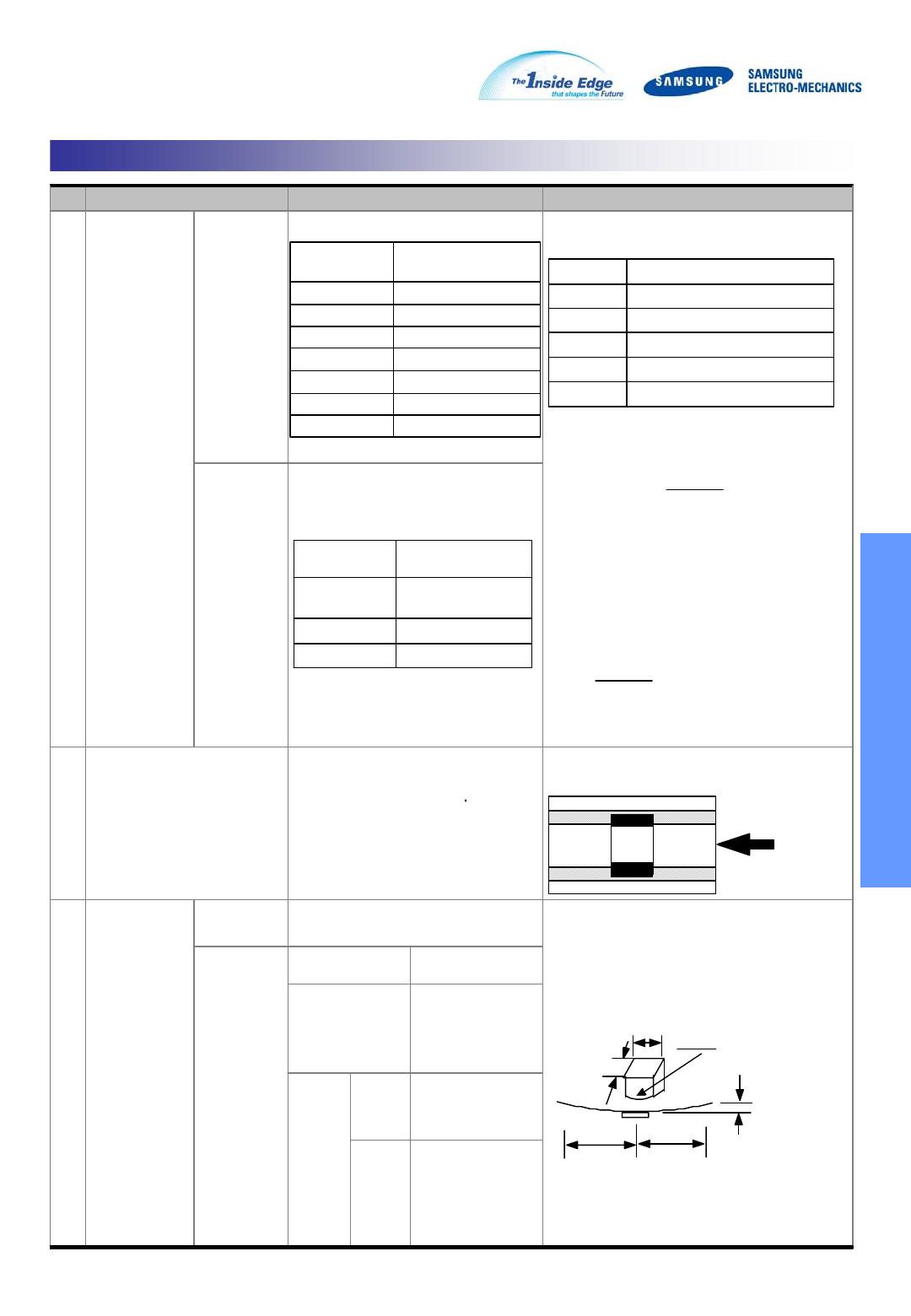
Apperance No mechanical damage shall occur. Solder Temperature : 270±5
Dip Time : 10±1 sec.
Each termination shall be fully immersed and
preheated as below :
Leave the capacitor in ambient condition for
specified time* before measurement
*24±2hours(Class
)
24 ± 2 hours (Class
)
Capacitance
Characteristics Capacitance Change
Class
Within ±2.5% or
±0.25
whichever is
larger
Class
A(X5R)/
B(X7R)
Within ±7.5%
X(X6S) Within ±15%
F Within ±20%
Q
(Class
)
Capacitance
30
:Q
1000
<30
:Q
400+20×C
(C: Capacitance)
Tan
δ
(Class
)
Within the specified initial value
Insulation
Resistance
Within the specified initial value
Withstanding
Voltage
Within the specified initial value
12
Vibration
Test
Appearance No mechanical damage shall occur.
The capacitor shall be subjected to a
Harmonic Motion having a total amplitude of
1.5mm changing frequency from 10Hz to 55Hz
and back to 10Hz In 1 min.
Repeat this for 2hours each in 3 mutually
perpendicular directions
Capacitance
Characteristics Capacitance Change
Class
Within ±2.5% or
±0.25
whichever is
larger
Class
A(X5R)/
B(X7R)
Within ±5%
X(X6S) Within ±10%
F(Y5V) Within ±20%
Q
(Class
)
Within the specified initial value
Tan
δ
(Class
)
Within the specified initial value
Insulation
Resistance
Within the specified initial value
STEP TEMP.(
) TIME(SEC.)
1 80~100 60
2 150~180 60
Solder Sn-3Ag-0.5Cu 63Sn-37Pb
Solder
Temp.
245±5
235±5
Flux RMA Type
Dip Time 3±0.3 sec. 5±0.5 sec.
Pre-heating at 80~120
for 10~30 sec.
RELIABILTY TEST CONDITION
General Capacitors
NO
ITEM PERFORMANCE TEST CONDITION
13
Humidity
(Steady
State)
Appearance No mechanical damage shall occur. Temperature : 40±2
Relative humidity : 90~95 %RH
Duration time : 500 +12/-0 hr.
Leave the capacitor in ambient
condition for specified time* before
measurement.
CLASS
:24±2Hr.
CLASS
:24±2Hr.
Capacitance
Characteristics Capacitance Change
Class
Within ±5.0% or ±0.5
whichever is larger
Class
A(X5R)/
B(X7R)/
X(X6S)
Within ±12.5%
F(Y5V)
Within ±30%
Q
CLASS
Capacitance
30
:Q
350
10
Capacitance <30
:Q
275 + 2.5×C
Capacitance < 10pF : Q
200 + 10×C (C: Capacitance)
Tan
δ
CLASS
1. Characteristic : A(X5R),
B(X7R)
0.05max (16V and over)
0.075max (10V)
0.075max
(6.3V except Table 1)
0.125max*
(refer to Table 1)
2. Characteristic : F(Y5V)
0.075max (25V and over)
0.1max (16V, C<1.0
)
0.125max(16V, C
1.0
)
0.15max (10V)
0.195max (6.3V)
Insulation
Resistance
1,000
or 50
·
whichever is smaller.
14
Moisture
Resistance
Appearance No mechanical damage shall occur.
Applied Voltage : rated voltage
Temperature : 40±2
Humidity : :90~95%RH
Duration Time : 500 +12/-0 Hr.
Charge/Discharge Current : 50
max.
Perform the initial measurement according to
Note1 .
Perform the final measurement according to
Note2.
Capacitance
Characteristics Capacitance Change
Class
Within ±5.0% or ±0.5
whichever is larger
Class
A(X5R)/
B(X7R)/
X(X6S)
Within ±12.5%
Within ±12.5%
Within ±30%
F(Y5V)
Within ±30%
Within ±30%
Q
(Class
)
Capacitance
30
:Q
200
Capacitance <30
:Q
100 + 10/C (C: Capacitance)
Tan
δ
(Class
)
1. Characteristic : A(X5R),
B(X7R)
0.05max (16V and over)
0.075max (10V)
0.075max
(6.3V except Table 1)
0.125max*
(refer to Table 1)
2. Characteristic : F(Y5V)
0.075max (25V and over)
0.1max (16V, C<1.0
)
0.125max(16V, C
1.0
)
0.15max (10V)
0.195max (6.3V)
X(X6S) 0.11max (6.3V and below)
Insulation
Resistance
500
or 25
·
whichever is smaller.
RELIABILTY TEST CONDITION

CL10B104KB8NNNC

Mfr. #:
Manufacturer:
Description:
CAP CER 0.1UF 50V X7R 0603
Lifecycle:
New from this manufacturer.
Delivery:
DHL FedEx Ups TNT EMS
Payment:
T/T Paypal Visa MoneyGram Western Union