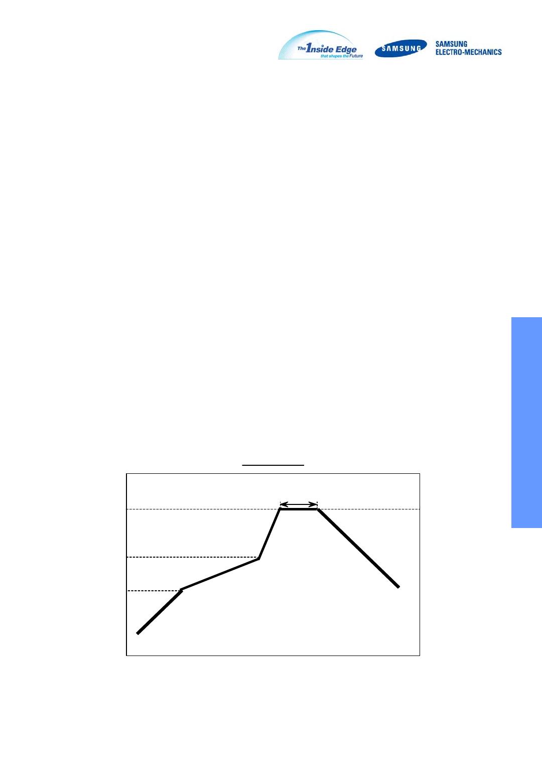
Too much
Solder
Not enough
Solder
Cracks tend to occur due
to large stress
Weak holding force may
cause bad connections or
detaching of the capacitor
Good
support pin
force
nozzle
General Capacitors
Bending Stress
When double-sided circuit boards are used, MLCCs first are mounted and soldered onto one side of the
board. When the MLCCs are mounted onto the other side,
it is important to support the board as shown in the illustration. If the circuit board is not supported,
the crack occur to the ready-installed MLCCs by the bending stress.
Manual Soldering
Manual soldering can pose a great risk of creating thermal cracks in chip capacitors.
The hot soldering iron tip comes into direct contact with the end terminations, and operator's
carelessness may cause the tip of the soldering iron to come into direct contact with the ceramic
body of the capacitor.
Therefore the soldering iron must be handled carefully, and close attention must be paid
to the selection of the soldering iron tip and to temperature control of the tip.
Amount of Solder
Pre-heating
Gradual cooling
in the air
Soldering
Temp.(℃ )
260+0/-5℃
10sec.max.
Time(sec)
Reflow
200℃
150℃
General Capacitors
Cooling
Natural cooling using air is recommended. If the chips are dipped into solvent for cleaning, the
temperature difference(T) must be less than 100
Cleaning
If rosin flux is used, cleaning usually is unnecessary. When strongly activated flux is used, chlorine in
the flux may dissolve into some types of cleaning fluids, thereby affecting the chip capacitors. This
means that the cleaning fluid must be carefully selected, and should always be new.
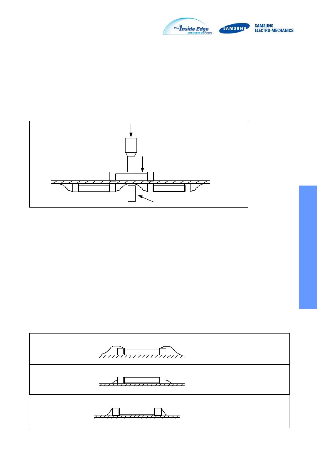
Notes for Separating Multiple, Shared PC Boards.
A multi-PC board is separated into many individual circuit boards after soldering has been completed.
If the board is bent or distorted at the time of separation, cracks may occur in the chip capacitors.
Carefully choose a separation method that minimizes the bending often circuit board.
Recommended Soldering Profile
T
i) 1206(3216) and
below
: 150
max.
Pre-heating
Gradual Cooling
in the air
Soldering
Temp. (
)
Pre-heating
Temp. (
)
120 sec. min.
260±3
5 sec. max.
Time (sec.)
Flow
Soldering Iron
Variation of Temp.
Soldering
Temp (
)
Pre-heating
Time (Sec)
Soldering
Time(Sec)
Cooling
Time(Sec)
T
130
300
±
10
max
60
4
-
Condition of Iron facilities
Wattage Tip Diameter Soldering Time
20W Max 3
Max 4SecMax
* Caution - Iron Tip Should Not Contact With Ceramic Body Directly.
General Capacitors

CL10B104KB8NNNC

Mfr. #:
Manufacturer:
Description:
CAP CER 0.1UF 50V X7R 0603
Lifecycle:
New from this manufacturer.
Delivery:
DHL FedEx Ups TNT EMS
Payment:
T/T Paypal Visa MoneyGram Western Union