OP113/OP213/OP413
Rev. F | Page 16 of 24
8
1
4
3
2
2
OUTPUT
+
V
S
+ = 5V 12
V
R1
5
k
R2
5
k
V
S
+
C2
1µF
R3
2.5k
C1
0.1µF
R4
100
+
1/2
OP213
0
0286-045
Figure 46. False Ground Generator
LOW NOISE VOLTAGE REFERENCE
Few reference devices combine low noise and high output drive
capabilities.
Figure 47 shows the OPx13 family used as a two-
pole active filter that band limits the noise of the 2.5 V reference.
Total noise measures 3 V p-p.
8
1
4
3
2
1/2
OP213
5V
+
OUTPUT
2.5V
+
10k10k
6
2
5V
IN
OUT
4
GND
REF43
+
3µV p-p NOISE
10µF
C2
10µF
00286-046
Figure 47. Low Noise Voltage Reference
5 V ONLY STEREO DAC FOR MULTIMEDIA
The OPx13 family’s low noise and single supply capability are
ideally suited for stereo DAC audio reproduction or sound
synthesis applications such as multimedia systems.
Figure 48
shows an 18-bit stereo DAC output setup that is powered from a
single 5 V supply. The low noise preserves the 18-bit dynamic
range of the AD1868. For DACs that operate on dual supplies,
the OPx13 family can also be powered from the same supplies.
18-BIT
DAC
18-BIT
DAC
V
REF
V
REF
AGND
1
2
3
4
5
6
7
8
16
15
14
13
12
11
10
9
V
L
LL
DL
CK
DR
LR
DGND
V
B
R
V
S
V
O
R
V
O
L
V
B
L
AD1868
8
1
47k
+
100pF
7.68k
7.68k
7.68k
7.68k
330pF
9.76k
330pF
9.76k
6
5
7
100pF
47k
+
5
V
SUPPLY
1/2
OP213
1/2
OP213
18-BIT
SERIAL
REG.
18-BIT
SERIAL
REG.
+
+
+
+
220µF
LEFT
CHANNEL
OUTPUT
+
+
3
2
4
RIGHT
CHANNEL
OUTPUT
220µF
0
0286-047
Figure 48. 5 V Only 18-Bit Stereo DAC
OP113/OP213/OP413
Rev. F | Page 17 of 24
LOW VOLTAGE HEADPHONE AMPLIFIERS
Figure 49 shows a stereo headphone output amplifier for the
AD1849 16-bit SOUNDPOR stereo codec device.
1
The
pseudo-reference voltage is derived from the common-mode
voltage generated internally by the AD1849, thus providing a
convenient bias for the headphone output amplifiers.
5V
5k
OPTIONAL
GAIN
1k
5V
5k
29
19
31
10k
LOUT1L
LOUT1R
CMOUT
AD1849
16
47k
HEADPHONE
LEFT
HEADPHONE
RIGHT
16
47k
+
OPTIONAL
GAIN
1k
V
REF
10µF
V
REF
10k
10µF
L VOLUME
CONTROL
1/2
OP213
1/2
OP213
1/2
OP213
R VOLUME
CONTROL
V
REF
220µF
+
220µF
+
+
+
00286-048
Figure 49. Headphone Output Amplifier for Multimedia Sound Codec
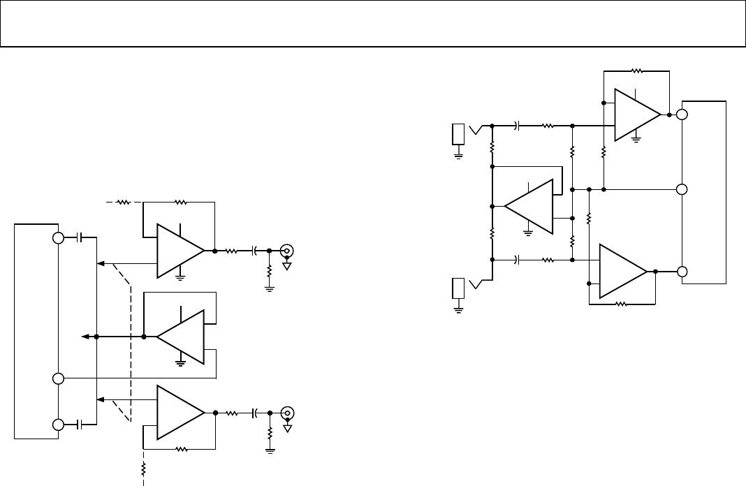
LOW NOISE MICROPHONE AMPLIFIER FOR
MULTIMEDIA
The OPx13 family is ideally suited as a low noise microphone
preamp for low voltage audio applications.
Figure 50 shows a
gain of 100 stereo preamp for the AD1849 16-bit SOUNDPORT
stereo codec chip. The common-mode output buffer serves as a
phantom power driver for the microphones.
5V
10k
50
20
10010k
5V
20
50
10k
10k
100
15
17
MINL
MINR
CMOUT
AD1849
19
LEFT
ELECTRET
C
ONDENSE
R
MIC
INPUT
10µF
+
10µF
+
1/2
OP213
1/2
OP213
+
RIGHT
ELECTRET
CONDENSER
MIC
INPUT
+
1/2
OP213
+
00286-049
Figure 50. Low Noise Stereo Microphone Amplifier for Multimedia Sound
Codec
PRECISION VOLTAGE COMPARATOR
With its PNP inputs and 0 V common-mode capability, the
OPx13 family can make useful voltage comparators. There is
only a slight penalty in speed in comparison to IC comparators.
However, the significant advantage is its voltage accuracy. For
example, V
OS
can be a few hundred microvolts or less, combined
with CMRR and PSRR exceeding 100 dB, while operating from
a 5 V supply. Standard comparators like the 111/311 family
operate on 5 V, but not with common mode at ground, nor with
offset below 3 mV. Indeed, no commercially available single-
supply comparator has a V
OS
less than 200 V.
1
SOUNDPORT is a registered trademark of Analog Devices, Inc.
OP113/OP213/OP413
Rev. F | Page 18 of 24
Figure 51 shows the OPx13 family response to a 10 mV
overdrive signal when operating in open loop. The top trace
shows the output rising edge has a 15 s propagation delay,
whereas the bottom trace shows a 7 s delay on the output
falling edge. This ac response is quite acceptable in many
applications.
5V
0V
–2.5V
+2.5V
±10mV OVERDRIVE
1/2
OP113
10
90
100
0%
2V
2V
+
100
25k
t
r
=
t
f
= 5ms
5µs
0
0286-050
Figure 51. Precision Comparator
The low noise and 250 V (maximum) offset voltage enhance
the overall dc accuracy of this type of comparator. Note that zero-
crossing detectors and similar ground referred comparisons can be
implemented even if the input swings to −0.3 V below ground.
9V
+IN
–IN
OUT
9V
00286-051
Figure 52. OP213 Simplified Schematic

OP113ES-REEL

Mfr. #:
Manufacturer:
Analog Devices Inc.
Description:
Instrumentation Amplifiers Low Noise Low Drift SGL-Supply
Lifecycle:
New from this manufacturer.
Delivery:
DHL FedEx Ups TNT EMS
Payment:
T/T Paypal Visa MoneyGram Western Union