ADV7123
Rev. D | Page 17 of 24
CIRCUIT DESCRIPTION AND OPERATION
The ADV7123 contains three 10-bit DACs, with three input
channels, each containing a 10-bit register. Also integrated
on board the part is a reference amplifier. The CRT control
functions,
BLANK
and
SYNC
, are integrated on board the
ADV7123.
DIGITAL INPUTS
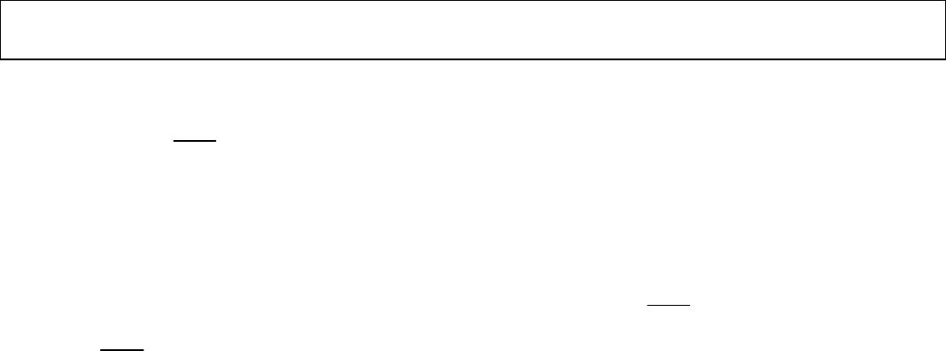
There are 30 bits of pixel data (color information), R0 to R9, G0
to G9, and B0 to B9, latched into the device on the rising edge
of each clock cycle. This data is presented to the three 10-bit
DACs and then converted to three analog (RGB) output
waveforms (see Figure 22).
CLOCK
DATA
DIGITAL INPUTS
(R9 TO R0, G9 TO G0,
B9 TO B0,
SYNC, BLANK)
ANALOG OUTPUTS
(IOR, IOR, IOG, IOG,
IOB, IOB)
00215-022
Figure 22. Video Data Input/Output
The ADV7123 has two additional control signals that are latched
to the analog video outputs in a similar fashion.
BLANK
and
SYNC
are each latched on the rising edge of CLOCK to maintain
synchronization with the pixel data stream.
The
BLANK
and
SYNC
functions allow for the encoding of
these video synchronization signals onto the RGB video output.
This is done by adding appropriately weighted current sources
to the analog outputs, as determined by the logic levels on the
BLANK
and
SYNC
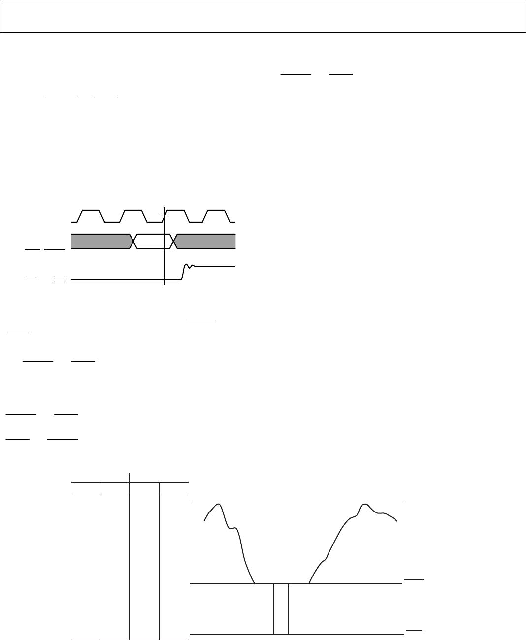
digital inputs. shows the analog
output, RGB video waveform of the ADV7123. The influence of
Figure 23
SYNC
and
BLANK
on the analog video waveform is illustrated.
Table 9 details the resultant effect on the analog outputs of
BLANK
and
SYNC
.
All these digital inputs are specified to accept TTL logic levels.
CLOCK INPUT
The CLOCK input of the ADV7123 is typically the pixel clock
rate of the system. It is also known as the dot rate. The dot rate,
and thus the required CLOCK frequency, is determined by the
on-screen resolution, according to the following equation:
Dot Rate = (Horiz Res) × (Vert Res) × (Refresh Rate)/
(Retrace Factor)
where:
Horiz Res is the number of pixels per line.
Vert Res is the number of lines per frame.
Refresh Rate is the horizontal scan rate. This is the rate at which
the screen must be refreshed, typically 60 Hz for a noninterlaced
system, or 30 Hz for an interlaced system.
Retrace Factor is the total blank time factor. This takes into
account that the display is blanked for a certain fraction of the
total duration of each frame (for example, 0.8).
Therefore, for a graphics system with a 1024 × 1024 resolution,
a noninterlaced 60 Hz refresh rate, and a retrace factor of 0.8,
Dot Rate = 1024 × 1024 × 60/0.8 = 78.6 MHz
The required CLOCK frequency is thus 78.6 MHz.
All video data and control inputs are latched into the ADV7123
on the rising edge of CLOCK, as described in the Digital Inputs
section. It is recommended that the CLOCK input to the
ADV7123 be driven by a TTL buffer (for example, 74F244).
RED AND BLUE
NOTES
1. OUTPUTS CONNECTED TO A DOUBLY TERMINATED 75Ω LOAD.
2. V
REF
= 1.235V, R
SET
= 530Ω.
3. RS-343 LEVELS AND TOLERANCES ASSUMED ON ALL LEVELS.
mA V
18.67 0.7
00
mA V
26.0 0.975
WHITE LEVEL
BLANK LEVEL
SYNC LEVEL
7.2 0.271
00
GREEN
00215-023
Figure 23. Typical RGB Video Output Waveform