13
82C54
MODE 2: RATE GENERATOR
This Mode functions like a divide-by-N counter. It is typically
used to generate a Real Time Clock Interrupt. OUT will
initially be high. When the initial count has decremented to 1,
OUT goes low for one CLK pulse. OUT then goes high
again, the Counter reloads the initial count and the process
is repeated. Mode 2 is periodic; the same sequence is
repeated indefinitely. For an initial count of N, the sequence
repeats every N CLK cycles.
GATE = 1 enables counting; GATE = 0 disables counting. If
GATE goes low during an output pulse, OUT is set high
immediately. A trigger reloads the Counter with the initial
count on the next CLK pulse; OUT goes low N CLK pulses
after the trigger. Thus the GATE input can be used to
synchronize the Counter.
After writing a Control Word and initial count, the Counter will
be loaded on the next CLK pulse. OUT goes low N CLK
pulses after the initial count is written. This allows the
Counter to be synchronized by software also.
Writing a new count while counting does not affect the current
counting sequence. If a trigger is received after writing a new
count but before the end of the current period, the Counter will
be loaded with the new count on the next CLK pulse and
counting will continue from the end of the current counting
cycle.
MODE 3: SQUARE WAVE MODE
Mode 3 is typically used for Baud rate generation. Mode 3 is
similar to Mode 2 except for the duty cycle of OUT. OUT will
initially be high. When half the initial count has expired, OUT
goes low for the remainder of the count. Mode 3 is periodic;
the sequence above is repeated indefinitely. An initial count
of N results in a square wave with a period of N CLK cycles.
GATE = 1 enables counting; GATE = 0 disables counting. If
GATE goes low while OUT is low, OUT is set high
immediately; no CLK pulse is required. A trigger reloads the
Counter with the initial count on the next CLK pulse. Thus
the GATE input can be used to synchronize the Counter.
After writing a Control Word and initial count, the Counter will
be loaded on the next CLK pulse. This allows the Counter to
be synchronized by software also.
Writing a new count while counting does not affect the
current counting sequence. If a trigger is received after
writing a new count but before the end of the current half-
cycle of the square wave, the Counter will be loaded with the
new count on the next CLK pulse and counting will continue
from the new count. Otherwise, the new count will be loaded
at the end of the current half-cycle.
NNNN
0
2
0
1
0
3
0
2
0
1
0
3
0
3
NNNN
0
2
0
2
0
3
0
2
0
1
0
3
0
3
NNNN
0
3
0
2
0
1
0
5
0
4
0
3
0
4
WR
CLK
GATE
OUT
CW = 14 LSB = 3
WR
CLK
GATE
OUT
CW = 14 LSB = 3
WR
CLK
GATE
OUT
CW = 14 LSB = 4 LSB = 5
FIGURE 11. MODE 2
NNNN
0
2
0
4
0
2
0
4
0
2
0
4
0
2
0
4
0
4
0
2
NNN N
0
4
0
2
0
5
0
2
0
5
0
4
0
2
0
5
0
5
0
2
NNN N
0
2
0
4
0
2
0
2
0
2
0
4
0
2
0
4
0
4
0
2
WR
CLK
GATE
OUT
CW = 16 LSB = 4
WR
CLK
GATE
OUT
WR
CLK
GATE
OUT
CW = 16 LSB = 5
CW = 16 LSB = 4
FIGURE 12. MODE 3
14
82C54
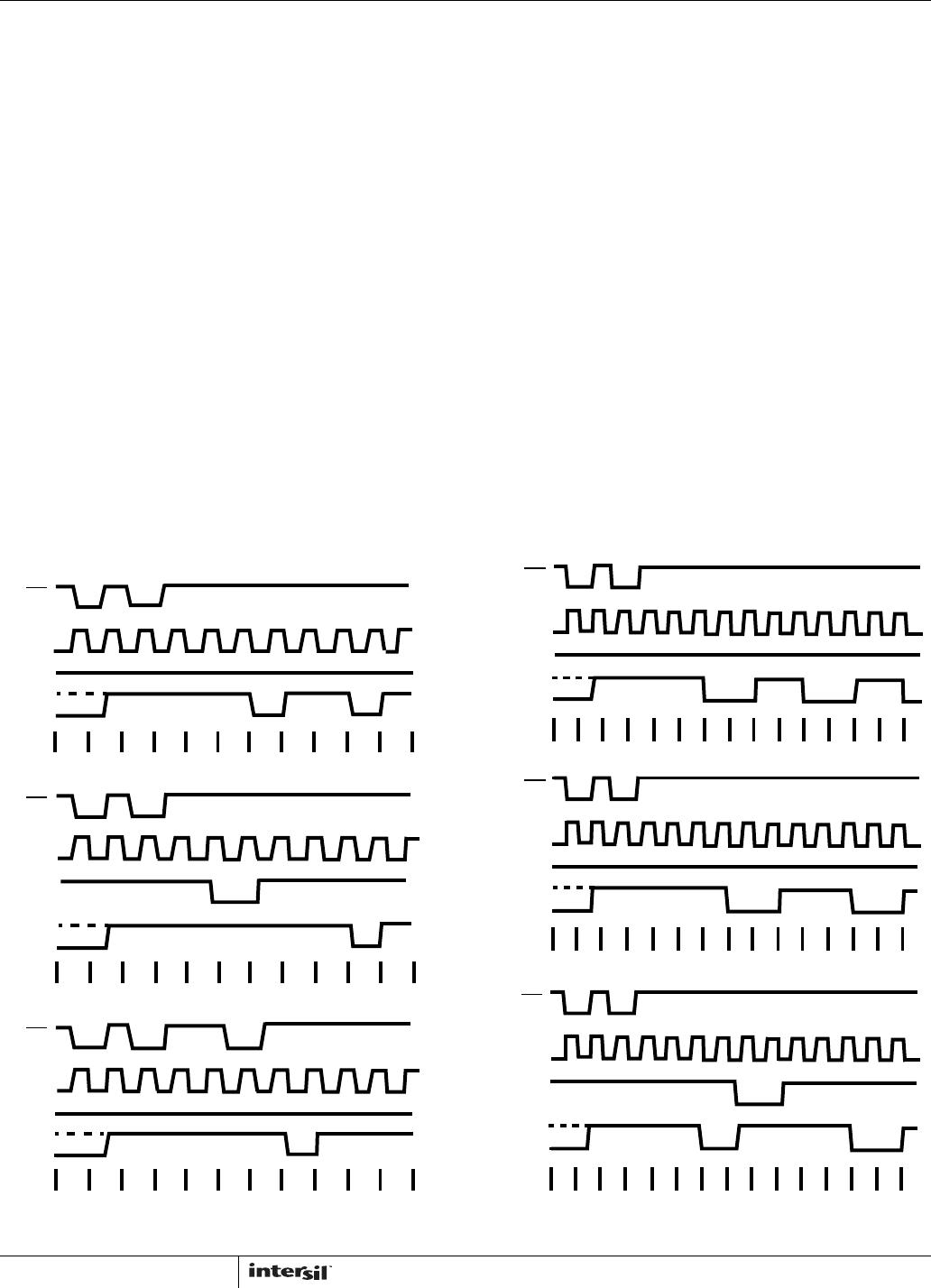
Mode 3 Is Implemented As Follows
EVEN COUNTS - OUT is initially high. The initial count is
loaded on one CLK pulse and then is decremented by two
on succeeding CLK pulses. When the count expires, OUT
changes value and the Counter is reloaded with the initial
count. The above process is repeated indefinitely.
ODD COUNTS - OUT is initially high. The initial count is loaded
on one CLK pulse, decremented by one on the next CLK pulse,
and then decremented by two on succeeding CLK pulses.
When the count expires, OUT goes low and the Counter is
reloaded with the initial count. The count is decremented by
three on the next CLK pulse, and then by two on succeeding
CLK pulses. When the count expires, OUT goes high again and
the Counter is reloaded with the initial count. The above
process is repeated indefinitely. So for odd counts, OUT will be
high for (N + 1)/2 counts and low for (N - 1)/2 counts.
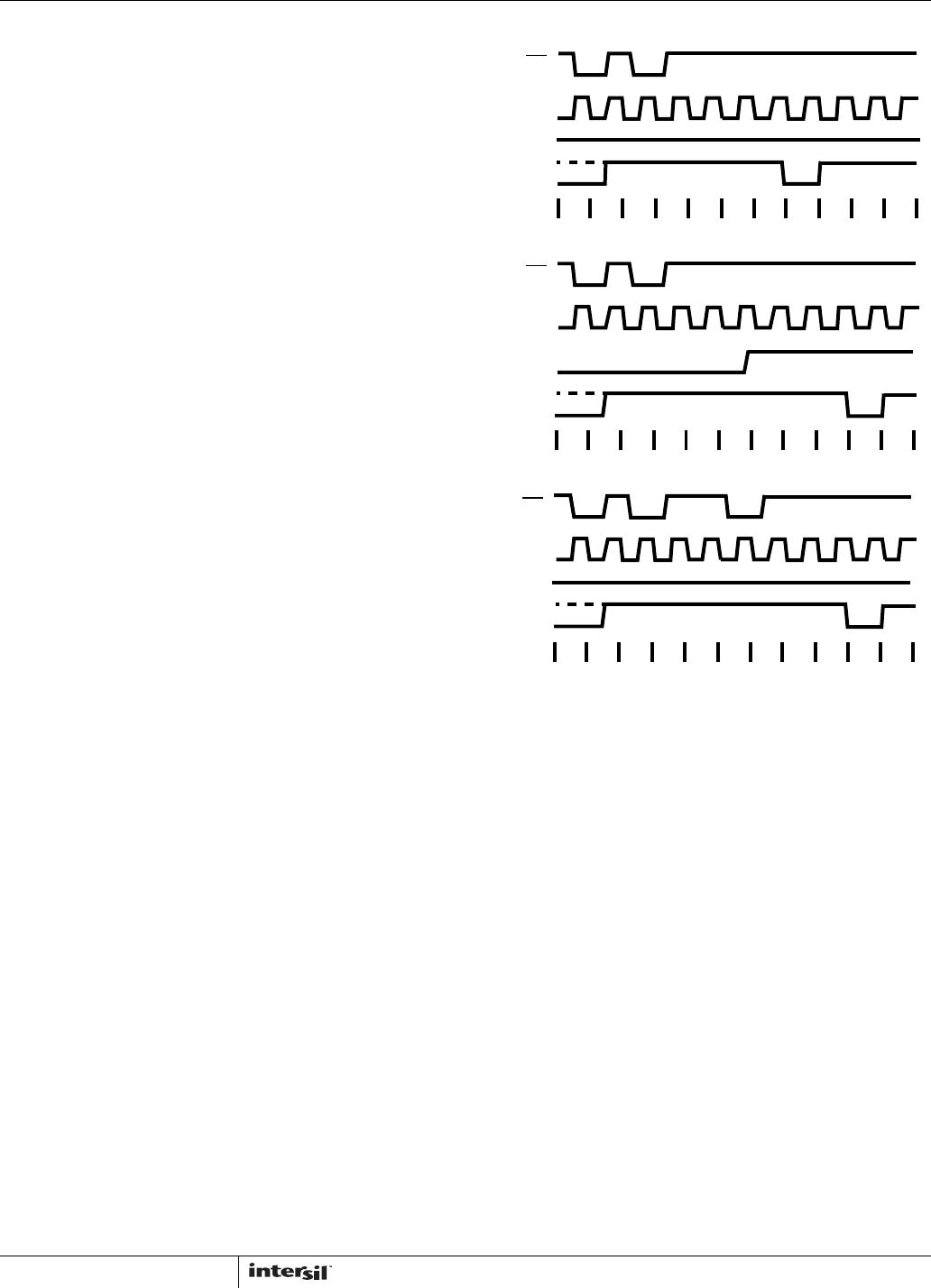
MODE 4: SOFTWARE TRIGGERED MODE
OUT will be initially high. When the initial count expires, OUT
will go low for one CLK pulse then go high again. The
counting sequence is “Triggered” by writing the initial count.
GATE = 1 enables counting; GATE = 0 disables counting.
GATE has no effect on OUT.
After writing a Control Word and initial count, the Counter will be
loaded on the next CLK pulse. This CLK pulse does not
decrement the count, so for an initial count of N, OUT does not
strobe low until N + 1 CLK pulses after the initial count is
written.
If a new count is written during counting, it will be loaded on
the next CLK pulse and counting will continue from the new
count. If a two-byte count is written, the following happens:
1. Writing the first byte has no effect on counting.
2. Writing the second byte allows the new count to be
loaded on the next CLK pulse.
This allows the sequence to be “retriggered” by software. OUT
strobes low N + 1 CLK pulses after the new count of N is
written.
MODE 5: HARDWARE TRIGGERED STROBE
(RETRIGGERABLE)
OUT will initially be high. Counting is triggered by a rising
edge of GATE. When the initial count has expired, OUT will
go low for one CLK pulse and then go high again.
After writing the Control Word and initial count, the counter
will not be loaded until the CLK pulse after a trigger. This
CLK pulse does not decrement the count, so for an initial
count of N, OUT does not strobe low until N + 1 CLK pulses
after trigger.
A trigger results in the Counter being loaded with the initial
count on the next CLK pulse. The counting sequence is
triggerable. OUT will not strobe low for N + 1 CLK pulses
after any trigger GATE has no effect on OUT.
If a new count is written during counting, the current counting
sequence will not be affected. If a trigger occurs after the
new count is written but before the current count expires, the
NNNN
0
2
0
1
0
0
FF
FF
FF
FE
FF
FD
0
3
WR
CLK
GATE
OUT
CW = 18 LSB = 3
WR
CLK
GATE
OUT
WR
CLK
GATE
OUT
CW = 18 LSB = 3
CW = 18 LSB = 3
NNN
0
3
0
2
0
1
0
2
0
1
0
0
FF
FF
NN NN
0
3
0
3
0
2
0
1
0
0
FF
FF
0
3
LSB = 2
N
FIGURE 13. MODE 4
15
Counter will be loaded with new count on the next CLK pulse
and counting will continue from there.
Operation Common To All Modes
Programming
When a Control Word is written to a Counter, all Control
Logic, is immediately reset and OUT goes to a known initial
state; no CLK pulses are required for this.
Gate
The GATE input is always sampled on the rising edge of
CLK. In Modes 0, 2, 3 and 4 the GATE input is level
sensitive, and logic level is sampled on the rising edge of
CLK. In modes 1, 2, 3 and 5 the GATE input is rising-edge
sensitive. In these Modes, a rising edge of Gate (trigger)
sets an edge-sensitive flip-flop in the Counter. This flip-flop is
then sampled on the next rising edge of CLK. The flip-flop is
reset immediately after it is sampled. In this way, a trigger
will be detected no matter when it occurs - a high logic level
does not have to be maintained until the next rising edge of
CLK. Note that in Modes 2 and 3, the GATE input is both
edge-and level-sensitive.
Counter
New counts are loaded and Counters are decremented on
the falling edge of CLK.
The largest possible initial count is 0; this is equivalent to 2
16
for binary counting and 10
4
for BCD counting.
The counter does not stop when it reaches zero. In Modes 0,
1, 4, and 5 the Counter “wraps around” to the highest count,
either FFFF hex for binary counting or 9999 for BCD
counting, and continues counting. Modes 2 and 3 are
periodic; the Counter reloads itself with the initial count and
continues counting from there.
NNNN
0
3
0
2
0
1
0
0
FF
FF
0
3
WR
CLK
GATE
OUT
CW = 1A LSB = 3
NNNN
0
3
0
2
0
3
0
2
0
1
NNNN
0
3
0
2
0
1
0
0
FF
FF
FF
FE
WR
CLK
GATE
OUT
CW = 1A LSB = 3
WR
CLK
GATE
OUT
CW = 1A LSB = 3
N
NN
0
0
FF
FF
LSB = 5
N
0
5
0
4
FIGURE 14. MODE 5
SIGNAL
STATUS
MODES
LOW OR
GOING LOW RISING HIGH
0 Disables Counting - Enables Counting
1 - 1) Initiates
Counting
2) Resets output
after next clock
-
2 1) Disables
counting
2) Sets output
immediately high
Initiates Counting Enables Counting
3 1) Disables
counting
2) Sets output
immediately high
Initiates Counting Enables Counting
4 1) Disables
Counting
- Enables Counting
5 - Initiates Counting -
FIGURE 15. GATE PIN OPERATIONS SUMMARY
MODE MIN COUNT MAX COUNT
010
110
220
320
410
510
NOTE: 0 is equivalent to 2
16
for binary counting and 10
4
for BCD
counting.
FIGURE 16. MINIMUM AND MAXIMUM INITIAL COUNTS
82C54

CS82C54-10Z

Mfr. #:
Manufacturer:
Renesas / Intersil
Description:
Timers & Support Products PERIPH PRG-CNTR 5V 10MHZ 28PLCC COM
Lifecycle:
New from this manufacturer.
Delivery:
DHL FedEx Ups TNT EMS
Payment:
T/T Paypal Visa MoneyGram Western Union