Electrical specifications VND5N07-E
8/22 DocID025077 Rev 2
t
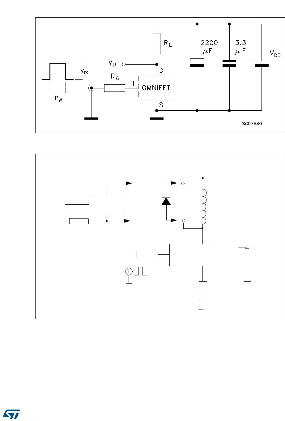
d(on)
Turn-on delay time
V
DD
=15V; I
D
= 2.5 A;
V
gen
=10V; R
gen
=1kΩ
150 250 ns
t
r
Rise time 400 600 ns
t
d(off)
Turn-off delay time 3900 5000 ns
t
f
Fall time 1100 1600 ns
(dI/dt)
on
Turn-on current slope
V
DD
=15V; I
D
= 2.5 A;
V
in
=10V; R
gen
=10Ω
80 A/µS
Q
i
Total input charge
V
DD
=12V; I
D
= 2.5 A;
V
IN
=10V
18 nC
1. Parameters guaranteed by design / characterization.
Table 8. Source drain diode
Symbol Parameter Test conditions Min. Typ. Max. Unit
V
SD
(1)
1. Pulsed: pulse duration = 300µs, duty cycle 1.5%.
Forward on voltage I
SD
= 2.5 A; V
IN
=0V 1.6 V
t
rr
(2)
2. Parameters guaranteed by design / characterization.
Reverse recovery time
I
SD
= 2.5 A; dI/dt = 100 A/µs;
V
DD
=30V
150 ns
Q
rr
(2)
Reverse recovery
charge
0.3 µC
I
RRM
(2)
Reverse recovery
current
5.7 A
Table 9. Protections (-40°C < T
j
< 150°C, unless otherwise specified)
Symbol Parameter Test conditions Min. Typ. Max. Unit
I
lim
Drain current limit
V
IN
=10V; V
DS
=13V 3.5 5 7 A
V
IN
=5V; V
DS
=13V 3.5 5 7 A
t
dlim
(1)
1. Parameters guaranteed by design / characterization.
Step response current
limit
V
IN
=10V 15 20 µS
V
IN
=5V 40 60 µS
T
jsh
(1)
Overtemperature
shutdown
150 °C
T
jrs
(1)
Overtemperature reset 135 °C
I
gf
(1)
Fault sink current
V
IN
=10V; V
DS
=13V 50 mA
V
IN
=5V; V
DS
=13V 20 mA
E
as
(1)
Single pulse
avalanche energy
Starting T
j
= 25°C; V
DD
=20V;
V
IN
=10V; R
gen
=1kΩ;
L=10mH
0.2 J
Table 7. Switching
(1)
Symbol Parameter Test conditions Min. Typ. Max. Unit