13
LTC1435
APPLICATIONS INFORMATION
WUU
U
Foldback Current Limiting
As described in Power MOSFET and D1 Selection, the
worst-case dissipation for either MOSFET occurs with a
short-circuited output, when the synchronous MOSFET
conducts the current limit value almost continuously. In
most applications this will not cause excessive heating,
even for extended fault intervals. However, when heat
sinking is at a premium or higher R
DS(ON)
MOSFETs are
being used, foldback current limiting should be added to
reduce the current in proportion to the severity of the fault.
Foldback current limiting is implemented by adding diode
D
FB
between the output and the I
TH
pin as shown in the
Functional Diagram. In a hard short (V
OUT
= 0V) the
current will be reduced to approximately 25% of the
maximum output current. This technique may be used for
all applications with regulated output voltages of 1.8V or
greater.
SFB Pin Operation
When the SFB pin drops below its ground referenced
1.19V threshold, continuous mode operation is forced. In
continuous mode, the large N-channel main and synchro-
nous switches are used regardless of the load on the main
output.
In addition to providing a logic input to force continuous
synchronous operation, the SFB pin provides a means to
regulate a flyback winding output. Continuous synchro-
nous operation allows power to be drawn from the auxil-
iary windings without regard to the primary output load.
The SFB pin provides a way to force continuous synchro-
nous operation as needed by the flyback winding.
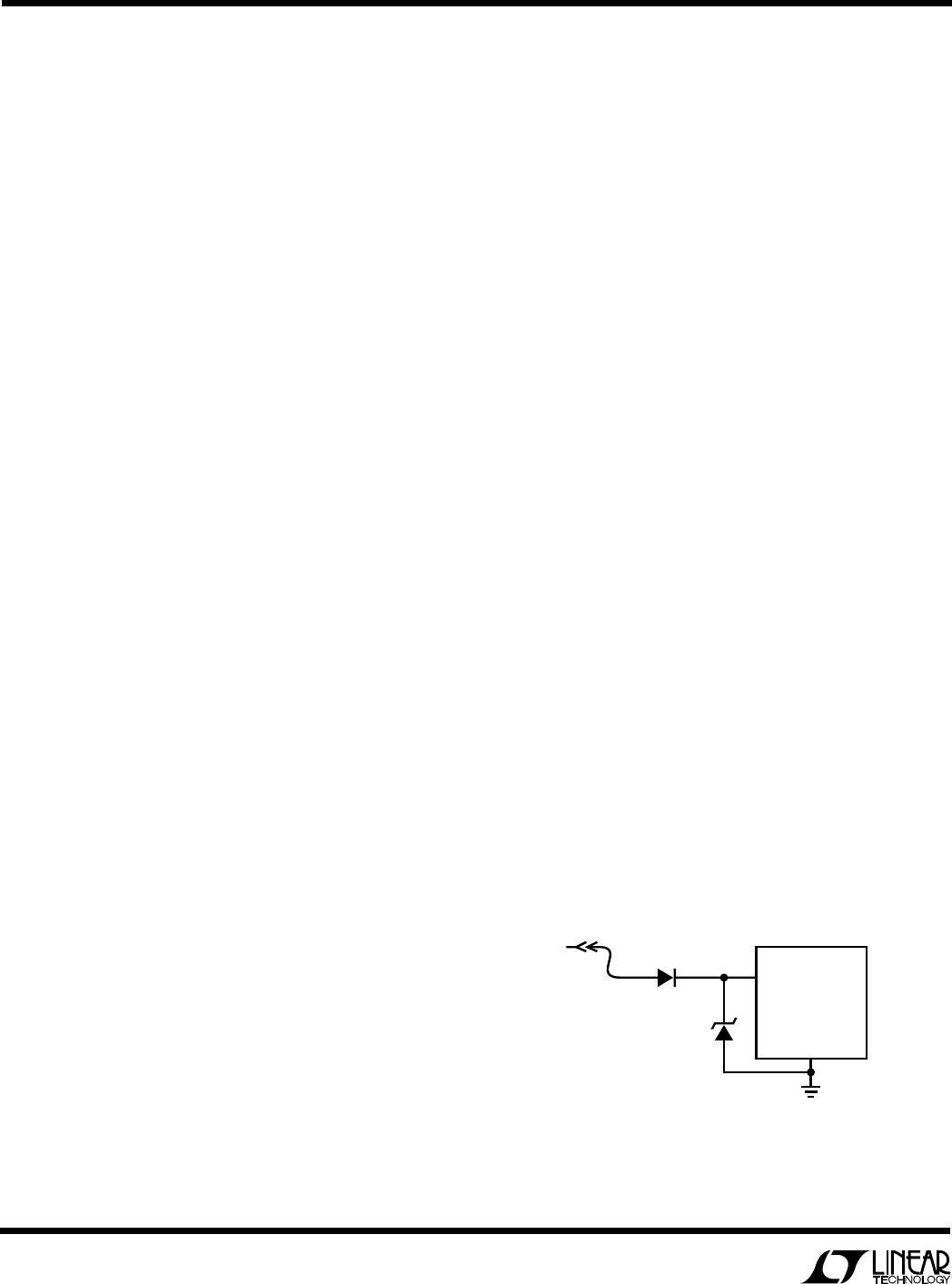
The secondary output voltage is set by the turns ratio of the
transformer in conjunction with a pair of external resistors
returned to the SFB pin as shown in Figure 4a. The
secondary regulated voltage, V
SEC
, in Figure 4a is given by:
VNV
R
R
SEC OUT
≈+
()
>+
1 1 19 1
6
5
.
where N is the turns ratio of the transformer and V
OUT
is
the main output voltage sensed by V
OSENSE
.
Efficiency Considerations
The efficiency of a switching regulator is equal to the
output power divided by the input power times 100%. It is
often useful to analyze individual losses to determine what
is limiting the efficiency and which change would produce
the most improvement. Efficiency can be expressed as:
Efficiency = 100% – (L1 + L2 + L3 + ...)
where L1, L2, etc. are the individual losses as a percentage
of input power.
Although all dissipative elements in the circuit produce
losses, four main sources usually account for most of the
losses in LTC1435 circuits. LTC1435 V
IN
current, INTV
CC
current, I
2
R losses, and topside MOSFET transition losses.
1. The V
IN
current is the DC supply current given in the
electrical characteristics which excludes MOSFET driver
and control currents. V
IN
current results in a small
(< 1%) loss which increases with V
IN
.
2. INTV
CC
current is the sum of the MOSFET driver and
control currents. The MOSFET driver current results
from switching the gate capacitance of the power
MOSFETs. Each time a MOSFET gate is switched from
low to high to low again, a packet of charge dQ moves
from INTV
CC
to ground. The resulting dQ/dt is a current
out of INT V
CC
which is typically much larger than the
control circuit current. In continuous mode,
I
GATECHG
= f(Q
T
+ Q
B
), where Q
T
and Q
B
are the gate
charges of the topside and bottom side MOSFETs.
By powering EXTV
CC
from an output-derived source,
the additional V
IN
current resulting from the driver and
control currents will be scaled by a factor of
Duty Cycle/Efficiency. For example, in a 20V to 5V
application, 10mA of INTV
CC
current results in approxi-
mately 3mA of V
IN
current. This reduces the midcurrent
loss from 10% or more (if the driver was powered
directly from V
IN
) to only a few percent.
3. I
2
R losses are predicted from the DC resistances of the
MOSFET, inductor and current shunt. In continuous
mode the average output current flows through L and
R
SENSE
, but is “chopped” between the topside main
14
LTC1435
APPLICATIONS INFORMATION
WUU
U
only solution is to limit the rise time of the switch drive so
that the load rise time is limited to approximately
(25)(C
LOAD
). Thus a 10µF capacitor would require a 250µs
rise time, limiting the charging current to about 200mA.
Automotive Considerations:
Plugging into the Cigarette Lighter
As battery-powered devices go mobile, there is a natural
interest in plugging into the cigarette lighter in order to
conserve or even recharge battery packs during operation.
But before you connect, be advised: you are plugging into
the supply from hell. The main battery line in an automo-
bile is the source of a number of nasty potential transients,
including load dump, reverse battery and double battery.
Load dump is the result of a loose battery cable. When the
cable breaks connection, the field collapse in the alternator
can cause a positive spike as high as 60V which takes
several hundred milliseconds to decay. Reverse battery is
just what it says, while double battery is a consequence of
tow truck operators finding that a 24V jump start cranks
cold engines faster than 12V.
The network shown in Figure 7 is the most straightfor-
ward approach to protect a DC/DC converter from the
ravages of an automotive battery line. The series diode
prevents current from flowing during reverse battery,
while the transient suppressor clamps the input voltage
during load dump. Note that the transient suppressor
should not conduct during double battery operation, but
must still clamp the input voltage below breakdown of the
converter. Although the LT1435 has a maximum input
voltage of 36V, most applications will be limited to 30V
by the MOSFET BV
DSS
.
MOSFET and the synchronous MOSFET. If the two
MOSFETs have approximately the same R
DS(ON)
, then
the resistance of one MOSFET can simply be summed
with the resistances of L and R
SENSE
to obtain I
2
R
losses. For example, if each R
DS(ON)
= 0.05,
R
L
= 0.15, and R
SENSE
= 0.05, then the total
resistance is 0.25. This results in losses ranging
from 3% to 10% as the output current increases from
0.5A to 2A. I
2
R losses cause the efficiency to drop at
high output currents.
4. Transition losses apply only to the topside MOSFET(s),
and only when operating at high input voltages (typi-
cally 20V or greater). Transition losses can be esti-
mated from:
Transition Loss = 2.5 (V
IN
)
1.85
(I
MAX
)(C
RSS
)(f)
Other losses, including C
IN
and C
OUT
ESR dissipative
losses, Schottky conduction losses during dead-time,
and inductor core losses, generally account for less
than 2% total additional loss.
Checking Transient Response
The regulator loop response can be checked by looking at
the load transient response. Switching regulators take
several cycles to respond to a step in DC (resistive) load
current. When a load step occurs, V
OUT
immediately shifts
by an amount equal to (I
LOAD
)(ESR), where ESR is the
effective series resistance of C
OUT
. I
LOAD
also begins to
charge or discharge C
OUT
which generates a feedback
error signal. The regulator loop then acts to return V
OUT
to
its steady-state value. During this recovery time V
OUT
can
be monitored for overshoot or ringing which would indi-
cate a stability problem. The I
TH
external components
shown in the Figure 1 circuit will provide adequate com-
pensation for most applications.
A second, more severe transient is caused by switching in
loads with large (>1µF) supply bypass capacitors. The
discharged bypass capacitors are effectively put in paral-
lel with C
OUT
, causing a rapid drop in V
OUT
. No regulator
can deliver enough current to prevent this problem if the
load switch resistance is low and it is driven quickly. The
Figure 7. Automotive Application Protection
1435 F07
50A I
PK
RATING
LTC1435
TRANSIENT VOLTAGE
SUPPRESSOR
GENERAL INSTRUMENT
1.5KA24A
V
IN
12V
15
LTC1435
APPLICATIONS INFORMATION
WUU
U
Design Example
As a design example, assume V
IN
= 12V(nominal), V
IN
=
22V(max), V
OUT
= 3.3V, I
MAX
= 3A and f = 250kHz, R
SENSE
and C
OSC
can immediately be calculated:
R
SENSE
= 100mV/3A = 0.033
C
OSC
= 1.37(10
4
)/250 – 11 = 43pF
Referring to Figure 3, a 10µH inductor falls within the
recommended range. To check the actual value of the
ripple current the following equation is used:
I
V
fL
V
V
L
OUT OUT
IN
=
()()
1–
The highest value of the ripple current occurs at the
maximum input voltage:
I
V
kHz H
V
V
L
=
µ
()
=
33
250 10
1
33
22
11
.
.
.2A
The power dissipation on the topside MOSFET can be
easily estimated. Choosing a Siliconix Si4412DY results
in: R
DS(ON)
= 0.042, C
RSS
= 100pF. At maximum input
voltage with T(estimated) = 50°C:
P
V
V
CC
V A pF kHz mW
MAIN
=
()
+
()
°− °
()
[]
()
+
()()( )( )
=
33
22
3 1 0 005 50 25 0 042
2 5 22 3 100 250 122
2
185
.
..
.
.
The most stringent requirement for the synchronous
N-channel MOSFET occurs when V
OUT
= 0 (i.e. short
circuit). In this case the worst-case dissipation rises to:
PI R
SYNC SC AVG DS ON
=
()
+
()
() ()
2
1
δ
With the 0.033 sense resistor I
SC(AVG)
= 4A will result,
increasing the Si4412DY dissipation to 950mW at a die
temperature of 105°C.
C
IN
is chosen for an RMS current rating of at least 1.5A at
temperature. C
OUT
is chosen with an ESR of 0.03 for low
output ripple. The output ripple in continuous mode will be
highest at the maximum input voltage. The output voltage
ripple due to ESR is approximately:
V
ORIPPLE
= R
ESR
(I
L
) = 0.03(1.112A) = 34mV
P-P
PC Board Layout Checklist
When laying out the printed circuit board, the following
checklist should be used to ensure proper operation of the
LTC1435. These items are also illustrated graphically in
the layout diagram of Figure 8. Check the following in your
layout:
1. Are the signal and power grounds segregated? The
LTC1435 signal ground pin must return to the (–) plate
of C
OUT
. The power ground connects to the source of
the bottom N-channel MOSFET, anode of the Schottky
diode, and (–) plate of C
IN
, which should have as short
lead lengths as possible.
2. Does the V
OSENSE
pin connect directly to the feedback
resistors? The resistive divider R1, R2 must be con-
nected between the (+) plate of C
OUT
and signal ground.
The 100pF capacitor should be as close as possible to
the LTC1435.
3. Are the SENSE
and SENSE
+
leads routed together with
minimum PC trace spacing? The filter capacitor be-
tween SENSE
+
and SENSE
should be as close as
possible to the LTC1435.
4. Does the (+) plate of C
IN
connect to the drain of the
topside MOSFET(s) as closely as possible? This capaci-
tor provides the AC current to the MOSFET(s).
5. Is the INTV
CC
decoupling capacitor connected closely
between
INTV
CC
and the power ground pin? This ca-
pacitor carries the MOSFET driver peak currents.
6. Keep the switching node SW away from sensitive small-
signal nodes. Ideally the switch node should be placed
at the furthest point from the LTC1435.
7. SGND should be exclusively used for grounding exter-
nal components on C
OSC
, I
TH
, V
OSENSE
and SFB pins.

LTC1435IG#PBF

Mfr. #:
Manufacturer:
Analog Devices / Linear Technology
Description:
Switching Voltage Regulators See P/N LTC1435AIG for Upgrade/
Lifecycle:
New from this manufacturer.
Delivery:
DHL FedEx Ups TNT EMS
Payment:
T/T Paypal Visa MoneyGram Western Union