83904-02 Data Sheet
©2016 Integrated Device Technology, Inc Revision A March 17, 20164
TABLE 4F. DC CHARACTERISTICS, TA = 0°C TO 70°C
Symbol Parameter Test Conditions Minimum Typical Maximum Units
V
IH
Input High Voltage
V
DD
= 3.3V ± 5% 2.2 V
DD
+ 0.3 V
V
DD
= 2.5V ± 5% 1.6 V
DD
+ 0.3 V
V
IL
Input Low Voltage
V
DD
= 3.3V ± 5% -0.3 1.3 V
V
DD
= 2.5V ± 5% -0.3 0.9 V
I
IH
Input High Current
CLK, CLK_
SEL0:1
V
DD
= 3.3V or 2.5V ± 5% 150 µA
OE V
DD
= 3.3V or 2.5V ± 5% 5 µA
I
IL
Input Low Current
CLK, CLK_
SEL0:1
V
DD
= 3.3V or 2.5V ± 5% -5 µA
OE V
DD
= 3.3V or 2.5V ± 5% -150 µA
V
OH
Output HighVoltage
V
DDO
= 3.3V ± 5%; NOTE 1 2.6 V
V
DDO
= 2.5V ± 5%; NOTE 1 1.8 V
V
DDO
= 1.8V ± 0.2V; NOTE 1 1.2 V
V
OL
Output Low Voltage
V
DDO
= 3.3V ± 5%; NOTE 1 0.6 V
V
DDO
= 2.5V ± 5%; NOTE 1 0.5 V
V
DDO
= 1.8V ± 0.2V; NOTE 1 0.4 V
NOTE 1: Outputs terminated with 50Ω to V
DDO
/2. See Parameter Measurement section, “Load Test Circuit” diagrams.
TABLE 5. CRYSTAL CHARACTERISTICS
Parameter Test Conditions Minimum Typical Maximum Units
Mode of Oscillation Fundamental
Frequency 12 38.88 MHz
Equivalent Series Resistance (ESR) 50 Ω
Shunt Capacitance 7pF
Drive Level 1mW
TABLE 4E. POWER SUPPLY DC CHARACTERISTICS, V
DD
= 2.5V±5%, V
DDO
= 1.8V±0.2V, TA = 0°C TO 70°C
Symbol Parameter Test Conditions Minimum Typical Maximum Units
V
DD
Power Supply Voltage 2.375 2.5 2.625 V
V
DDO
Output Supply Voltage 1.6 1.8 2.0 V
I
DD
Power Supply Current
No Load & XTALx selected @ 12MHz 3 mA
No Load & CLK selected 1 mA
I
DDO
Output Supply Current No Load & CLK selected 1 mA
83904-02 Data Sheet
©2016 Integrated Device Technology, Inc Revision A March 17, 20165
TABLE 6B. AC CHARACTERISTICS, V
DD
= 3.3V ± 5%, V
DDO
= 2.5V ± 5%, TA = 0°C TO 70°C
TABLE 6A. AC CHARACTERISTICS, V
DD
= V
DDO
= 3.3V ± 5%, TA = 0°C TO 70°C
Symbol Parameter Test Conditions Minimum Typical Maximum Units
f
MAX
Output Frequency
w/external XTAL 12 38.88 MHz
w/external CLK 200 MHz
tp
LH
Propagation Delay, Low-to-High; NOTE
1
1.4 1.9 2.4 ns
tsk(o) Output Skew; NOTE 2 40 ps
tsk(pp) Part-to-Part Skew; NOTE 2, 3 700 ps
tjit(Ø)
RMS Phase Jitter, Random;
NOTE 2, 4
25MHz, Integration Range:
100Hz – 1MHz
0.16 ps
t
R
/ t
F
Output Rise/Fall Time 20% to 80% 100 800 ps
odc
Output
Duty Cycle
w/external XTAL 45 55 %
w/external CLK ƒ < 150MHz 46 54 %
t
EN
Output Enable Time; NOTE 5 10 ns
t
DIS
Output Disable Time; NOTE 5 10 ns
NOTE 1: Measured from V
DD
/2 of the input to V
DDO
/2 of the output.
NOTE 2: This parameter is defi ned in accordance with JEDEC Standard 65.
NOTE 3: Defi ned as skew between outputs on different devices operating a the same supply voltages and
with equal load conditions. Using the same type of input on each device, the output is measured at V
DDO
/2.
NOTE 4: Phase jitter is dependent on the input source used.
NOTE 5: These parameters are guaranteed by characterization. Not tested in production.
Symbol Parameter Test Conditions Minimum Typical Maximum Units
f
MAX
Output Frequency
w/external XTAL 12 38.88 MHz
w/external CLK 200 MHz
tp
LH
Propagation Delay, Low-to-High; NOTE
1
1.5 2.0 2.5 ns
tsk(o) Output Skew; NOTE 2 40 ps
tsk(pp) Part-to-Part Skew; NOTE 2, 3 700 ps
tjit(Ø)
RMS Phase Jitter, Random;
NOTE 2, 4
25MHz, Integration Range:
100Hz - 1MHz
0.16 ps
t
R
/ t
F
Output Rise/Fall Time 20% to 80% 100 800 ps
odc
Output
Duty Cycle
w/external XTAL 45 55 %
w/external CLK ƒ < 150MHz 46 54 %
t
EN
Output Enable Time; NOTE 5 10 ns
t
DIS
Output Disable Time; NOTE 5 10 ns
NOTE 1: Measured from V
DD
/2 of the input to V
DDO
/2 of the output.
NOTE 2: This parameter is defi ned in accordance with JEDEC Standard 65.
NOTE 3: Defi ned as skew between outputs on different devices operating a the same supply voltages and
with equal load conditions. Using the same type of input on each device, the output is measured at V
DDO
/2.
NOTE 4: Phase jitter is dependent on the input source used.
NOTE 5: These parameters are guaranteed by characterization. Not tested in production.
83904-02 Data Sheet
©2016 Integrated Device Technology, Inc Revision A March 17, 20166
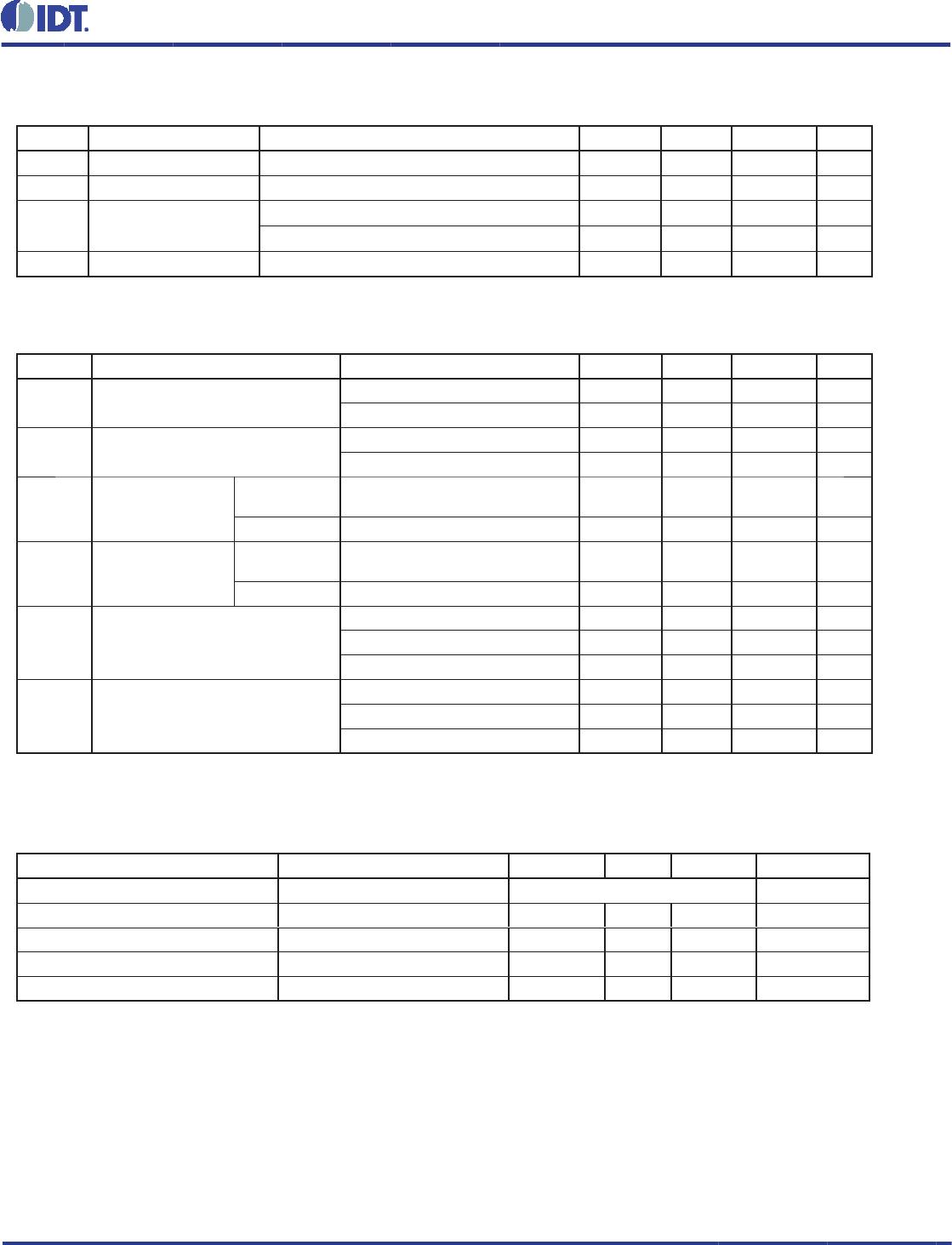
TABLE 6D. AC CHARACTERISTICS, V
DD
= V
DDO
= 2.5V ± 5%, TA = 0°C TO 70°C
TABLE 6C. AC CHARACTERISTICS, V
DD
= 3.3V ± 5%, V
DDO
= 1.8V±0.2V, TA = 0°C TO 70°C
Symbol Parameter Test Conditions Minimum Typical Maximum Units
f
MAX
Output Frequency
w/external XTAL 12 38.88 MHz
w/external CLK 200 MHz
tp
LH
Propagation Delay, Low-to-High; NOTE
1
1.7 2.2 2.7 ns
tsk(o) Output Skew; NOTE 2 40 ps
tsk(pp) Part-to-Part Skew; NOTE 2, 3 700 ps
tjit(Ø)
RMS Phase Jitter, Random;
NOTE 2, 4
25MHz, Integration Range:
100Hz - 1MHz
0.16 ps
t
R
/ t
F
Output Rise/Fall Time 20% to 80% 100 1000 ps
odc
Output
Duty Cycle
w/external XTAL 45 55 %
w/external CLK ƒ < 150MHz 46 54 %
t
EN
Output Enable Time; NOTE 5 10 ns
t
DIS
Output Disable Time; NOTE 5 10 ns
NOTE 1: Measured from V
DD
/2 of the input to V
DDO
/2 of the output.
NOTE 2: This parameter is defi ned in accordance with JEDEC Standard 65.
NOTE 3: Defi ned as skew between outputs on different devices operating a the same supply voltages and
with equal load conditions. Using the same type of input on each device, the output is measured at V
DDO
/2.
NOTE 4: Phase jitter is dependent on the input source used.
NOTE 5: These parameters are guaranteed by characterization. Not tested in production.
Symbol Parameter Test Conditions Minimum Typical Maximum Units
f
MAX
Output Frequency
w/external XTAL 12 38.88 MHz
w/external CLK 200 MHz
tp
LH
Propagation Delay, Low-to-High; NOTE
1
1.5 2.2 3.0 ns
tsk(o) Output Skew; NOTE 2 40 ps
tsk(pp) Part-to-Part Skew; NOTE 2, 3 700 ps
tjit(Ø)
RMS Phase Jitter, Random;
NOTE 2, 4
25MHz, Integration Range:
100Hz - 1MHz
0.20 ps
t
R
/ t
F
Output Rise/Fall Time 20% to 80% 100 800 ps
odc
Output
Duty Cycle
w/external XTAL 45 55 %
w/external CLK ƒ < 150MHz 48 52 %
t
EN
Output Enable Time; NOTE 5 10 ns
t
DIS
Output Disable Time; NOTE 5 10 ns
NOTE 1: Measured from V
DD
/2 of the input to V
DDO
/2 of the output.
NOTE 2: This parameter is defi ned in accordance with JEDEC Standard 65.
NOTE 3: Defi ned as skew between outputs on different devices operating a the same supply voltages and
with equal load conditions. Using the same type of input on each device, the output is measured at V
DDO
/2.
NOTE 4: Phase jitter is dependent on the input source used.
NOTE 5: These parameters are guaranteed by characterization. Not tested in production.

83904AG-02LF

Mfr. #:
Manufacturer:
IDT
Description:
Clock Buffer Fanout Buffer,2-XTAL /LVCMOS Input
Lifecycle:
New from this manufacturer.
Delivery:
DHL FedEx Ups TNT EMS
Payment:
T/T Paypal Visa MoneyGram Western Union

Products related to this Datasheet