Spec.No. JENF243H-9101A-01 P 3/ 13
MURATA MFG.CO.,LTD.
Reference Only
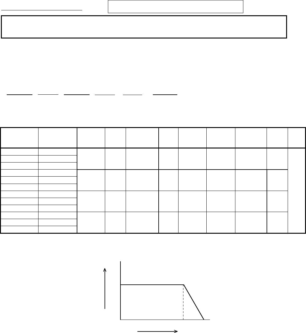
7.Electrical Performance
No. Item Specification Test Method
7.1 Insertion
Loss
Meet item 3.
Insertion Loss = -20 log E
1
/E
0
(dB)
E
0
: Level without FILTER (short)
E
1
: Level with FILTER
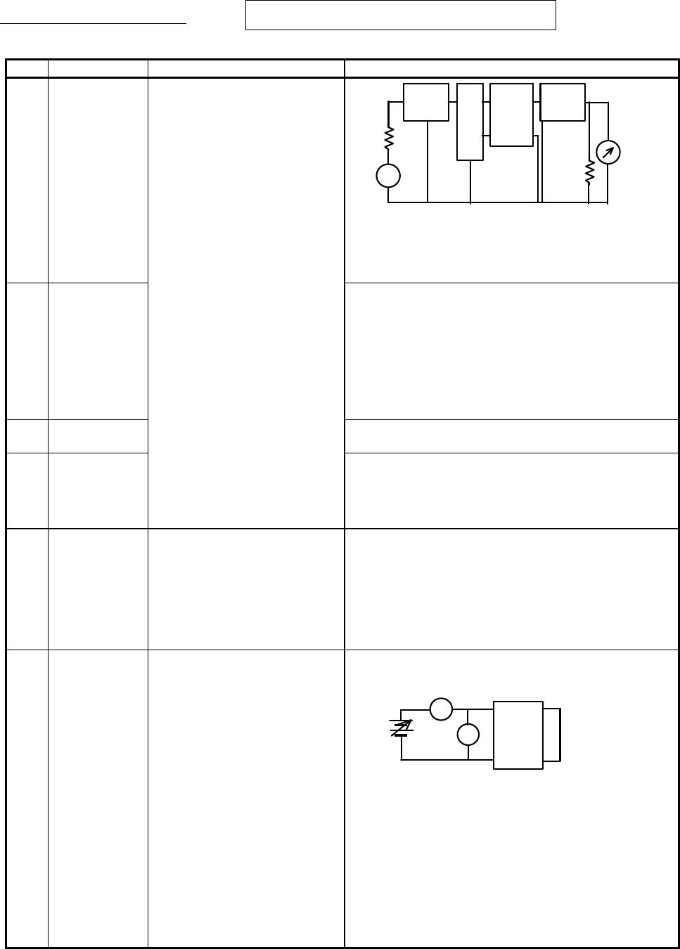
Measuring Equipment : Agilent 8753C or the equivalent
7.2 Capacitance
Measured by the following condition between
Terminal ①② and ③④. (see item 5.)
Frequency : 1 ± 0.1kHz (except BNX027)
120 ± 24kHz (BNX027)
Voltage : 1 V(rms) max. (except BNX027)
0.5±0.1V(rms) (BNX027)
Measuring Equipment :
HP 4278A or the equivalent (except BNX027)
HP 4284A or the equivalent (BNX027)
7.3 DC
Resistance
Measured by the way of 4 terminal method between① and
② and between ③ and ④. (see item 5.)
7.4 Insulation
Resistance
Measured at DC rated voltage between terminal
①② and ③④. (see item 5.)
Time : 60 s max
Charging current : 50 mA max.
Measuring Equipment : R8340A or the equivalent
7.5
Withstanding
Voltage
Filter shall be no failure.
Withstanding voltage shall be applied between terminal ①
② and ③④. (see item 5.)
Test Voltage : BNX024 125V(DC)
BNX025 62.5V(DC)
BNX026 125V(DC)
BNX027 40V(DC)
Time : 5 ± 1 s
Charging current : 50 mA max.
7.6 Voltage
Drop
Meet item 3. After soldering the part on the test substrate, measure
the voltage with passing the rated current as shown in the
schematic below.
Where the terminals of the part shall be connected as
follows:
Referring to the terminal No. shown in item 5,
connect terminal No. ② and ④ by soldering
copper wire with diameter more than 1mm /
length less than 6mm.
Then connect terminal No. ① as (1) and terminal
No. ③ as (2) the measurement circuit as
mentioned above.
The probe for measuring the voltage shall be
touched on the solder fillet of ①③.
A
V
Specimen
(1)
(2)
50
Ω
10dB
E
∗
Method of measurement based on MIL-STD-220
~
50
Ω
SG
50
Ω
50
Ω
10dB
Attenuator
Balun
Specimen
Attenuator
(1)
(2)
(3)
(4)