LTC3630
13
3630fd
For more information www.linear.com/LTC3630
applicaTions inForMaTion
Different core materials and shapes will change the size/
current and price/current relationship of an inductor. Toroid
or shielded pot cores in ferrite or permalloy materials are
small and do not radiate energy but generally cost more
than powdered iron core inductors with similar charac
-
teristics. The choice of which style inductor to use mainly
depends on the price versus size requirements and any
radiated field/EMI requirements. New designs for sur
face
mount inductors are available from Coiltronics, Coilcraft,
TDK, T
oko, and Sumida.
C
IN
and C
OUT
Selection
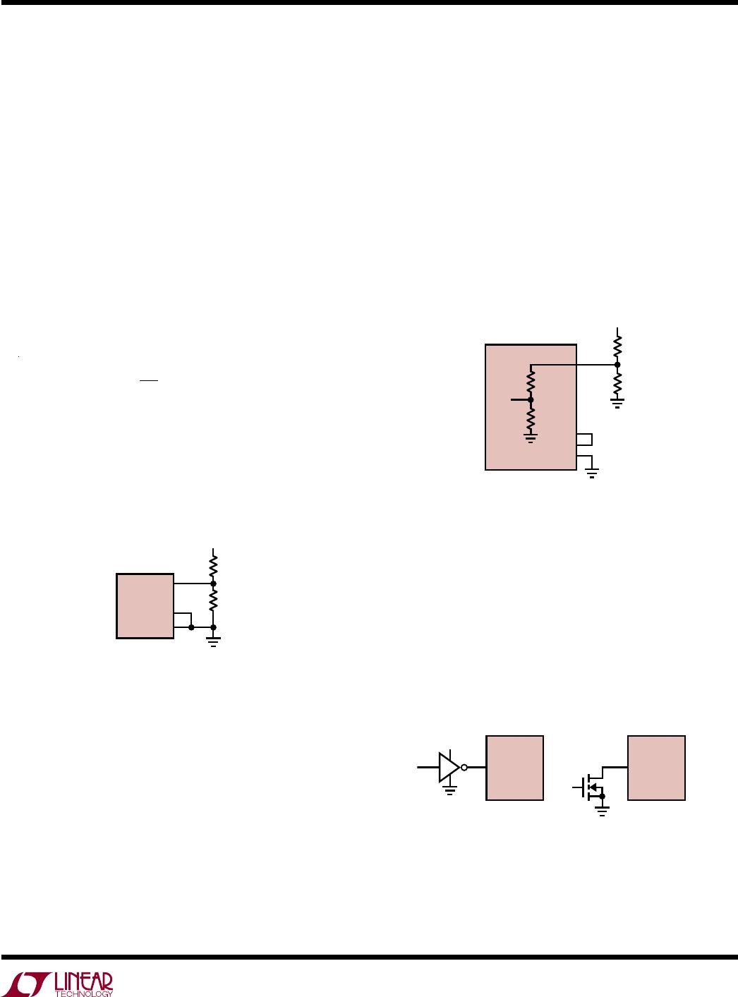
The input capacitor, C
IN
, is needed to filter the trapezoidal
current at the source of the top high side MOSFET. C
IN
should be sized to provide the energy required to charge
the inductor without causing a large decrease in input
voltage (V
IN
). The relationship between C
IN
and V
IN
is given by:
C
IN
>
L I
PEAK
2
2 V
IN
V
IN
It is recommended to use a larger value for C
IN
than
calculated by the above equation since capacitance de-
creases with applied voltage. In general, a 4.7µF X7R
ceramic capacitor is a good choice for C
IN
in most LTC3630
applications.
To
minimize large ripple voltage, a low ESR input capaci-
tor sized for the maximum RMS current should be used.
RMS current is given by:
I
RMS
= I
OUT(MAX)
V
OUT
V
IN
V
IN
V
OUT
1
This formula has a maximum at V
IN
= 2V
OUT
, where I
RMS
=
I
OUT
/2. This simple worst-case condition is commonly used
for design because even significant deviations do not offer
much relief. Note that ripple current ratings from capacitor
manufacturers are often based only on 2000 hours of life
which makes it advisable to further derate the capacitor,
or choose a capacitor rated at a higher temperature than
required. Several capacitors may also be paralleled to meet
size or height requirements in the design.
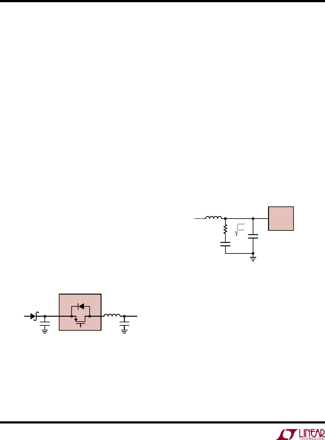
The output capacitor, C
OUT
, filters the inductors ripple
current and stores energy to satisfy the load current when
the LTC3630 is in sleep. The output ripple has a lower limit
of V
OUT
/160 due to the 5mV typical hysteresis of the feed-
back comparator. The time delay of the comparator adds
an additional ripple voltage that is a function of the load
current. During this delay time, the L
TC3630 continues to
switch and supply current to the output. The output ripple
can be approximated by:
V
OUT
I
PEAK
2
I
LOAD
4 10
6
C
OUT
+
V
OUT
160
The output ripple is a maximum at no load and approaches
lower limit of V
OUT
/160 at full load. Choose the output
capacitor C
OUT
to limit the output voltage ripple V
OUT
using the following equation:
C
OUT
I
PEAK
2 10
6
V
OUT
V
OUT
160
The value of the output capacitor must be large enough
to accept the energy stored in the inductor without a large
change in output voltage during a single switching cycle.
Setting this voltage step equal to 1% of the output voltage,
the output capacitor must be:
C
OUT
> 50 L
I
PEAK
V
OUT
2
Typically, a capacitor that satisfies the voltage ripple re-
quirement is adequate to filter the inductor ripple. To avoid
overheating, the output capacitor must also be sized to
handle the ripple current generated by the inductor. The
worst-case ripple current
in the output capacitor is given
by I
RMS
= I
PEAK
/2. Multiple capacitors placed in parallel
may be needed to meet the ESR and RMS current handling
requirements.
Dry tantalum, special polymer, aluminum electrolytic,
and ceramic capacitors are all available in surface mount
packages. Special polymer capacitors offer very low ESR
but have lower capacitance density than other types.
LTC3630
14
3630fd
For more information www.linear.com/LTC3630
applicaTions inForMaTion
Tantalum capacitors have the highest capacitance density
but it is important only to use types that have been surge
tested for use in switching power supplies. Aluminum
electrolytic capacitors have significantly higher ESR but
can be used in cost-sensitive applications provided that
consideration is given to ripple current ratings and long-
term reliability. Ceramic capacitors have excellent low ESR
characteristics but can have high voltage coefficient and
audible piezoelectric effects. The high quality factor (Q)
of ceramic capacitors in series with trace inductance can
also lead to significant input voltage ringing.
Input Voltage Steps
If the input voltage falls below the regulated output volt
-
age, the body diode of the internal high side MOSFET will
conduct current from the output supply to the input sup-
ply. If the input voltage falls rapidly, the voltage across the
inductor will be significant and may saturate the inductor
. A
large current will then flow through the high side MOSFET
body diode, resulting in excessive power dissipation that
may damage the part.
If rapid voltage steps are expected on the input supply, put
a small silicon or Schottky diode in series with the V
IN
pin
to prevent reverse current and inductor saturation, shown
below as D2 in Figure 5a. The diode should be sized for
a reverse voltage of greater than the input voltage, and to
withstand repetitive currents higher than the maximum
peak current of the LTC3630.
Ceramic Capacitors and Audible Noise
Higher value, lower cost ceramic capacitors are now be
-
coming available in smaller case sizes. Their high ripple
current, high voltage rating, and low ESR make them ideal
for switching regulator applications. However
, care must
be taken when these capacitors are used at the input and
output. When a ceramic capacitor is used at the input and
the power is supplied by a wall adapter through long wires,
a load step at the output can induce ringing at the input,
V
IN
. At best, this ringing can couple to the output and be
mistaken as loop instability. At worst, a sudden inrush
of current through the long wires can potentially cause
a voltage spike at V
IN
large enough to damage the part.
For application with inductive source impedance, such as
a long wire, an electrolytic capacitor or a ceramic capaci
-
tor with a series resistor may be required in parallel with
C
IN
to dampen the ringing of the input supply. Figure 5b
shows this circuit and the typical values required to
dampen the ringing.
Figure 5b. Series RC to Reduce V
IN
Ringing
Figure 5a. Preventing Current Flow to the Input
SW
INPUT
SUPPLY
LTC3630
C
OUT
3637 F05a
C
IN
V
OUT
V
IN
L
D2
R =
L
IN
C
IN
4 • C
IN
C
IN
L
IN
3630 F05b
V
IN
LTC3630
Ceramic capacitors are also piezoelectric sensitive. The
LTC3630’s burst frequency depends on the load current,
and in some applications at light load the LTC3630 can
excite the ceramic capacitor at audio frequencies, gen
-
erating audible noise. If the noise is unacceptable, use
a high performance tantalum or electrolytic capacitor at
the output.
LTC3630
15
3630fd
For more information www.linear.com/LTC3630
applicaTions inForMaTion
Output Voltage Programming
The LTC3630 has three fixed output voltage modes that
can be selected with the V
PRG1
and V
PRG2
pins and an
adjustable mode. The fixed output modes use an internal
feedback divider which enables higher efficiency, higher
noise immunity, and lower output voltage ripple for 5V,
3.3V and 1.8V applications. To select the fixed 5V output
voltage, connect V
PRG1
to SS and V
PRG2
to GND. For 3.3V,
connect V
PRG1
to GND and V
PRG2
to SS. For 1.8V, connect
both V
PRG1
and V
PRG2
to SS. For any of the fixed output
voltage options, directly connect the V
FB
pin to V
OUT
.
For the adjustable output mode (V
PRG1
= 0V, V
PRG2
= 0V),
the output voltage is set by an external resistive divider
according to the following equation:
V
OUT
= 0.8V 1+
R1
R2
The resistive divider allows the V
FB
pin to sense a fraction
of the output voltage as shown in Figure 6. The output
voltage can range from 0.8V to V
IN
. Be careful to keep the
divider resistors very close to the V
FB
pin to minimize the
trace length and noise pick-up on the sensitive V
FB
signal.
To avoid excessively large values of R1 in high output volt-
age applications (V
OUT
≥ 10V), a combination of external
and internal resistors can be used to set the output volt-
age. This has an additional benefit of increasing the noise
immunity on the V
FB
pin. Figure 7 shows the LTC3630
with the V
FB
pin configured for a 5V fixed output with an
external divider to generate a higher output voltage. The
internal 5M resistance appears in parallel with R2, and the
value of R2 must be adjusted accordingly. R2 should be
chosen to be less than 200k to keep the output voltage
variation less than 1% due to the tolerance of the LTC3630’s
internal resistor.
V
FB
V
OUT
R2
3630 F06
0.8V
R1
V
PRG1
V
PRG2
LTC3630
Figure 6. Setting the Output Voltage with External Resistors
4.2M
R1
5V
R2
3630 F07
V
OUT
800k
0.8V
V
FB
SS
V
PRG1
V
PRG2
LTC3630
Figure 7. Setting the Output Voltage with
External and Internal Resistors
RUN
SUPPLY
LTC3630
RUN
3630 F08
LTC3630
Figure 8. RUN Pin Interface to Logic
To minimize the no-load supply current, resistor values in
the megohm range may be used; however, large resistor
values should be used with caution. The feedback divider
is the only load current when in shutdown. If PCB leakage
current to the output node or switch node exceeds the load
current, the output voltage will be pulled up. In normal
operation, this is generally a minor concern since the load
current is much greater than the leakage.
RUN Pin and External Input Undervoltage Lockout
The RUN pin has two different threshold voltage levels.
Pulling the RUN pin below 0.7V puts the LTC3630 into a
low quiescent current shutdown mode (I
Q
~ 5µA). When
the RUN pin is greater than 1.21V, the controller is enabled.
Figure 8 shows examples of configurations for driving the
RUN pin from logic.

LTC3630HDHC#PBF

Mfr. #:
Manufacturer:
Analog Devices / Linear Technology
Description:
Switching Voltage Regulators High Efficiency, 65V 500mA Synchronous Step-Down Converter
Lifecycle:
New from this manufacturer.
Delivery:
DHL FedEx Ups TNT EMS
Payment:
T/T Paypal Visa MoneyGram Western Union