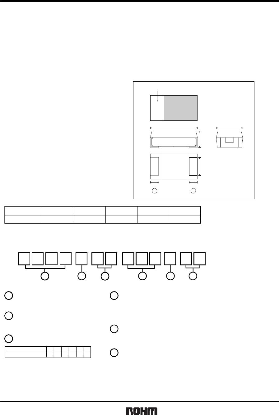
TCFG series P Case
Tantalum capacitors
Rev.A 3/13
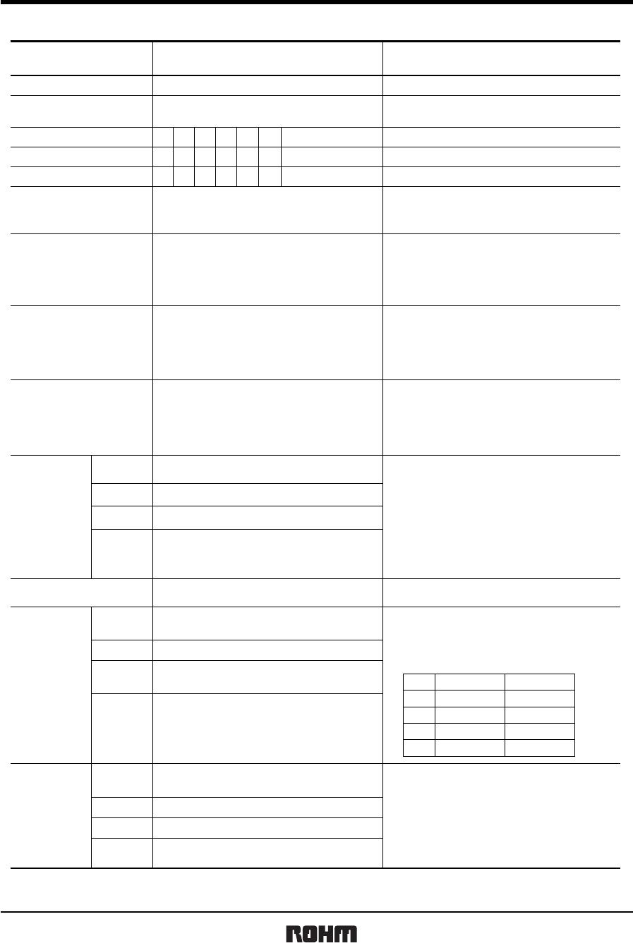
zCharacteristics
Item Performance
Test conditions
(based on JIS C5101-1 and JIS C5101-3)
Operating Temperature
Maximum operating temperature
with no voltage derating
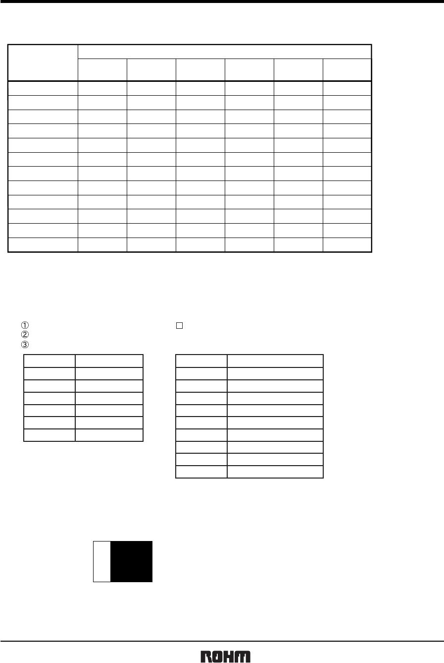
Rated Voltage (V.DC)
16106.34
Category Voltage (V.DC)
106.342.5
Surge Voltage
20
20
13
26
25
16
321385.2
DC leakage current
0.5µA or 0.01CV whichever is greater
(Shown in "Standard list")
As per 4.9 JIS C 5101-1
As per 4.5.1 JIS C 5101-3
As per 4.7 JIS C 5101-1
As per 4.5.2 JIS C 5101-3
As per 4.8 JIS C 5101-1
As per 4.5.3 JIS C 5101-3
As per 4.10 JIS C 5101-1
As per 4.5.4 JIS C 5101-3
As per 4.14 JIS C 5101-1
As per 4.6 JIS C 5101-3
As per 4.16 JIS C 5101-1
As per 4.10 JIS C 5101-3
As per 4.22 JIS C 5101-1
As per 4.12 JIS C 5101-3
Voltage : Rated voltage for 1 min
Capacitance tolerance
Shall be satisfied allowance range.
±
10%,
±
20%
Measuring frequency
Measuring voltage
Measuring circuit
Tangent of loss angle
(Df, tanδ)
Impedance
Shall be satisfied the voltage on "Standard list"
Dip in the solder bath
Solder temp
Duration
Repetition
Resistance to
soldering heat
There should be no significant abnormality.
The indications should be clear.
Appearance
Less than initial limit
L.C
Shall be satisfied the voltage on "Standard list"
at 125
°C
at 85
°C
at 85
°C
+85
°C
: 120
±
12Hz
: 0.5Vrms, +1.5V.DC
: DC Equivalent series circu
Measuring frequency
Measuring voltage
Measuring circuit
: 120
±
12Hz
: 0.5Vrms, +1.5V.DC
: DC Equivalent series circu
: 100
±
10kHz
: 0.5Vrms or less
: DC Equivalent series circuit
Measuring frequency
Measuring voltage
Measuring circuit
: 260
±5°C
: 5
±
0.5s
: 1
−55
°C to
+125
°C
Voltage reduction when temperature exceeds +85°C
Fail-Safe open unit actuation
Within
320
°C
− 20s
Repetition : 5 cycles (1 cycle : steps 1 to 4)
without discontinuation.
Temperature
cycle
There should be no significant abnormality.
Appearance
Less than initial limit
L.C
1 to 10µF : within
±
10
% of initial value
15 to 22µF : within
±
20
% of initial value
Within
±
10
% of initial value
∆C / C
tanδ
∆C / C
tanδ
Less than 150% of initial limit
Less than 150% of initial limit
Less than 150% of initial limit
Moisture
resistance
Appearance
Less than initial limit
L.C
There should be no significant abnormality.
The indications should be clear.
Temp. Time
1
Step
2
3
4
Room temp.
Room temp.
3min. or less
3min. or less
30 3min
+
−
30 3min
+
−
−55 3
°C
+
−
125 2°C
+
−
∆C / C
Within
±
20
% of initial value
tanδ
After leaving the sample under such atmospher
condition that the temperature and humidity are
60
±
2
°C
and 90 to 95%RH, respectively, for
500
±
12h level it at room temperature for 1 to 2h
and then measure the sample.
Dip in the solder bath
Solder temp : 320
±
5
°C