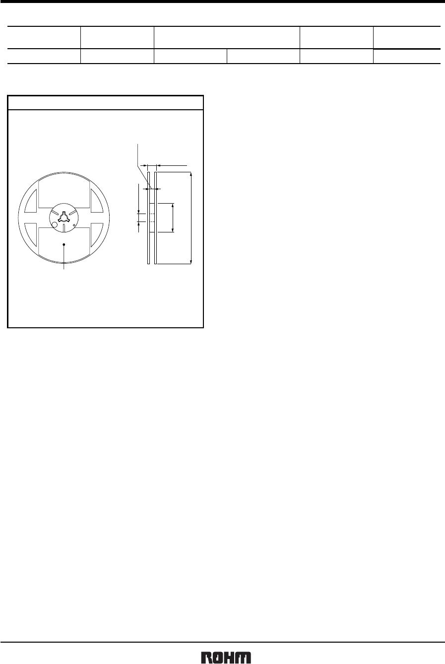
TCFG series P Case
Tantalum capacitors
Rev.A 9/13
(2) Leakage current-to-voltage ratio
0.01
0.1
1
0 20406080100
% OF RATED VOLTAGE (
V
R)
Fig.2
LEAKAGE CURRENT RATIO DCL / DCL
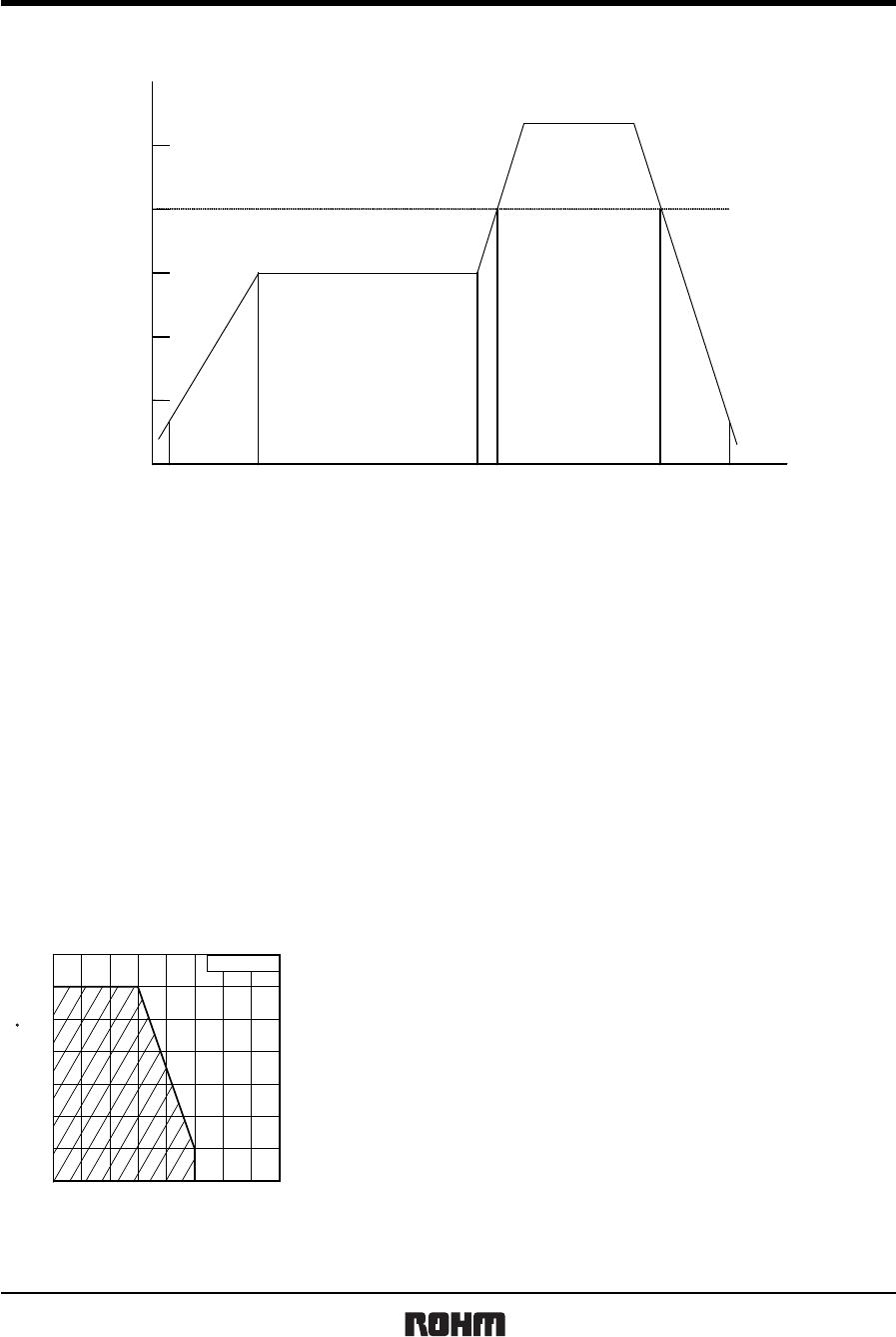
(3) Derating voltage as function of temperature
50
60
70
80
90
100
75 85 95 105 115 12
Fig.3
PERCENT OF 85°C RVDC1 (VR)
TEMPERATURE ( C)
85°C
125°C
Rated Voltage
4
6.3
10
16
20
5.0
8
13
20
26
2.5
4
6.3
10
13
3.4
5
9
12
16
Surge Voltage
Category Voltage Surge Voltage
(V.DC) (V.DC) (V.DC) (V.DC)
(4) Reliability
The malfunction rate of tantalum solid state electrolytic capacitors varies considerably depending on the conditions of
usage (ambient temperature, applied voltage, circuit resistance).
Formula for calculating malfunction rate
λp = λb × (π
E
× π
SR
× π
Q
× π
CV
)
λp
: Malfunction rate stemming from operation
λb
: Basic malfunction rate
π
E
: Environmental factors
π
SR
: Series resistance
π
Q
: Level of malfunction rate
π
CV
: Capacitance
For details on how to calculate the malfunction rate stemming from operation, see the tantalum solid state electrolytic
capacitors column in MIL-HDBK-217.