TCFG series P Case
Tantalum capacitors
Rev.A 10/13
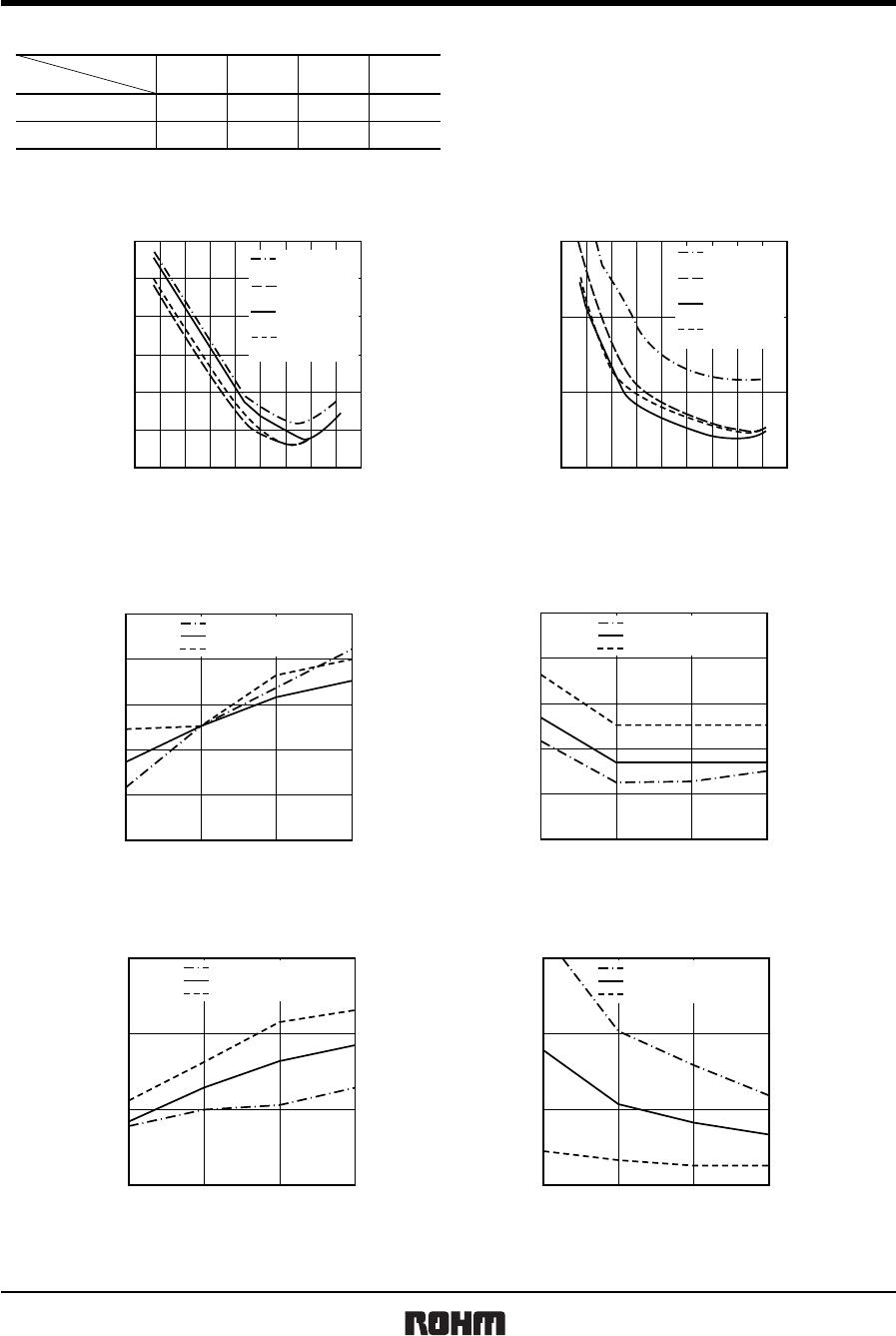
Malfunction rate as function of operating Malfunction rate as function of circuit resistance (Ω/V)
temperature and rated voltage
0.01
0.02
0.03
0.06
0.1
0.2
0.3
0.5
1.0
Ratio =
Rated Voltage
Applied Voltage
1.0
0.7
0.5
0.3
0.1
20 40 60 8
Fig.4
FAILURE RATE COEFFICIENT
OPERATING TEMPERATURE ( C)
0.4
0.6
0.8
1.0
2.0
4.0
6.0
0.1 0.2 0.60.4 3.01.0 2.0
RESISTANCE OF CIRCUIT (Ω / V)
Fig.5
RESISTANCE COEFFICIENT (π)
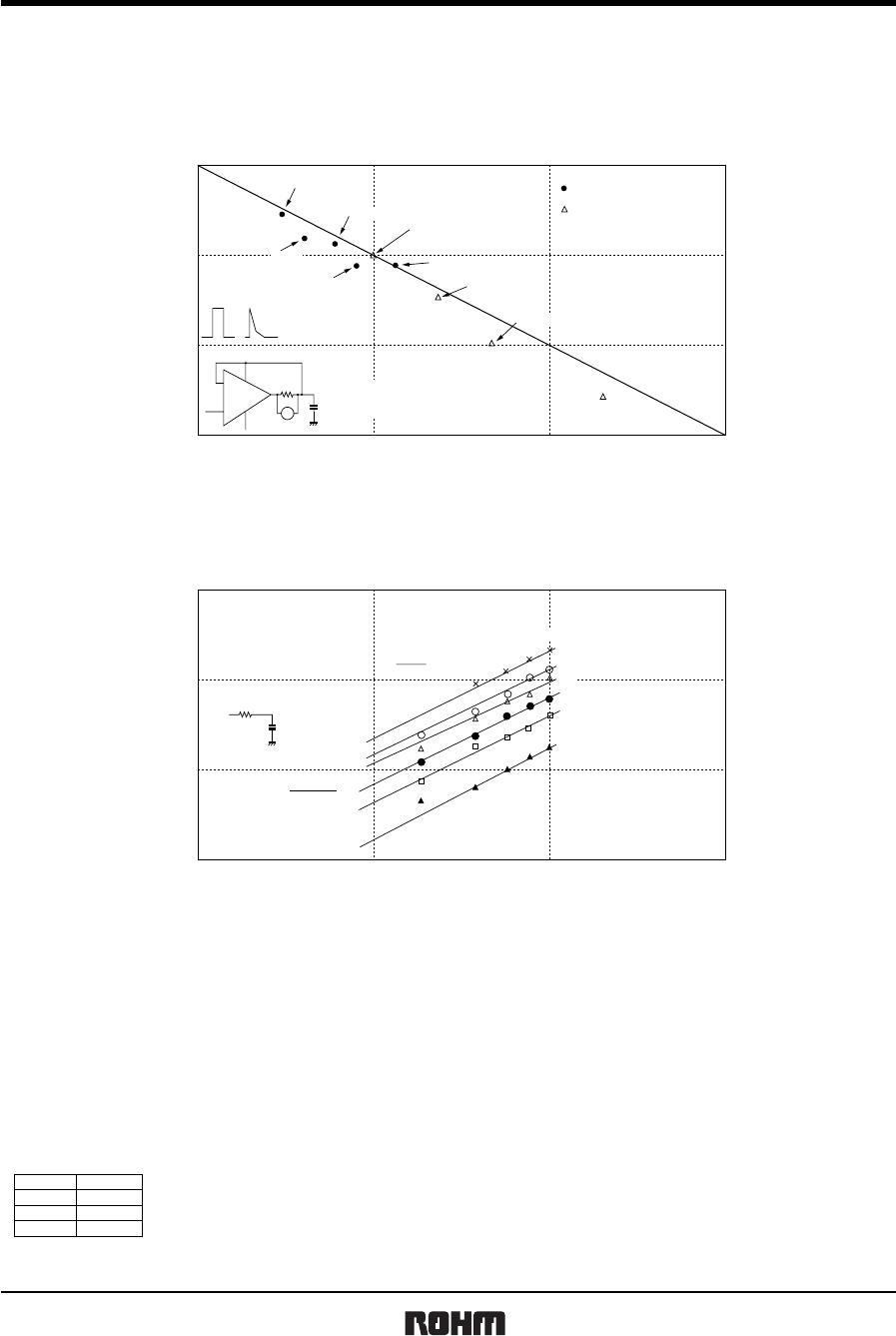
(5) External temperature vs. fuse blowout (6) Power vs. fuse blowout characteristics / Product
surface temperature
260
270
280
290
300
310
320
330
340
350
360
A case (3216)
P case (2012)
B case (3528)
failed
half failed
no failed
11010
OPERATING TIME (s)
Fig.6
EXTERNAL TEMPERATURE (°C)
0
10
20
30
40
50
60
70
80
90
100
024
no operating area
681097531
ELECTRIC POWER (W)
Fig.7
OPERATING TIME (s)
open-function characteristic
surface temp.
curve of the products
operating area
150
200
250
300
SURFACE TEMP. OF THE PRODUCT (°C)
A case (3216)
B case (3528)
P case (2012)
Note: Solder the chip at 300°C or less. If it is soldered using
a temperature higher than 300°C, open function built-in may operate.
(7) Maximum power dissipation
Warming of the capacitor due to ripple voltage balances with warming caused by Joule heating and by radiated heat.
Maximum allowable warming of the capacitor is to 5°C above ambient temperature. When warming exceeds 5°C, it can
damage the dielectric and cause a short circuit.
Power dissipation (P) = I
2
・R
Ripple current
P : As shown in table at right
R : Equivalent series resistance
Notes:
1. Please be aware that when case size is changed, maximum allowable power dissipation is reduced.
2. Maximum power dissipation varies depending on the package. Be sure to use a case which will keep warming within
the limits shown in the table below.