LTC2927
7
2927fb
0.8V
+
+
5
RAMPBUF
5
RAMP
2927 F06
5
V
CC
5
5
FB
5
ON
5
TRACK
1.2V
10μA
10μA
V
CC
1x
R
ONB
R
ONA
MASTER
SLAVE
DC/DC
C
RAMP
R
TB
R
FB
R
FA
R
TA
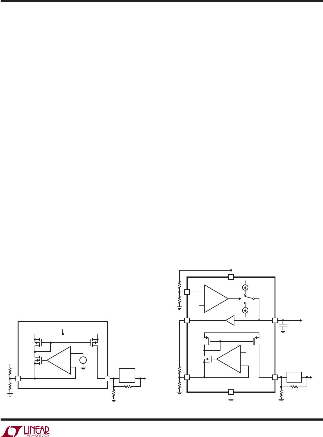
Figure 6. Simplifi ed Functional DiagramFigure 5. Simplifi ed Tracking Cell
0.8V
+
2927 F05
5
FB
5
TRACK
V
CC
MASTER
SLAVE
FB OUT
DC/DC
R
TB
R
FB
R
FA
R
TA
+
pin is mirrored at the FB pin to establish a voltage at the
output of the slave supply. The slave output voltage varies
with the master signal, enabling the slave supply to be
controlled as a function of the master signal with terms
set by R
TA
and R
TB
. By selecting appropriate values of
R
TA
and R
TB
, it is possible to generate any of the profi les
in Figures 1 to 4.
Controlling the Ramp-Up and Ramp-Down Behavior
The operation of the LTC2927 is most easily understood
by referring to the simplifi ed functional diagram in Figure
6. When the ON pin is low, the master signal at the RAMP
pin is pulled to ground. Since the current through R
TB
is
at its maximum when the master signal is low, the current
from FB is also at its maximum. This current drives the
slave output to its minimum voltage.
When the ON pin rises above 1.23V, the master signal
rises and the slave supply tracks the master signal. The
ramp rate is set by an external capacitor driven by a 10μA
current source at the RAMP pin. Alternatively, the RAMP
pin can be connected to a separate supply to be used as
the master signal.
In a properly designed system, when the master signal
has reached its maximum voltage the current from the
TRACK pin is zero. In this case, there is no current from
the FB pin and the LTC2927 has no effect on the output
voltage accuracy, transient response or stability of the
slave supply.
When the ON pin falls below V
ON(TH)
ΔV
ON(HYST)
, typi-
cally 1.225V, the RAMP pin pulls down with 10μA and the
master signal and slave supplies will fall at the same rate
as they rose previously.
The ON pin can be controlled by a digital I/O pin or it
can be used to monitor an input supply. By connecting a
resistive divider from an input supply to the ON pin, the
supplies will ramp up only after the monitored supply has
reached a preset voltage.
If a resistive divider is used to set the ON pin voltage, choose
values that will keep this voltage above the maximum ON
pin threshold voltage of 1.25V at the lowest operating
supply level.
The Ramp Buffer
The RAMPBUF pin provides a buffered version of the
RAMP pin voltage that drives the resistive divider on the
TRACK pin. The buffered master signal provides up to
2mA to drive the resistors.
Shutdown Output
In some applications it might be necessary to control
the shutdown or RUN/SS pins of the slave supplies. The
LTC2927 may not be able to supply the rated 1mA of current
from the FB pin when V
CC
is below 2.9V. If the slave power
supply is capable of operating at low input voltages, use
the open-drain SDO output to drive the SHDN or RUN/SS
pin of the slave supply (see Figure 7). This will hold the
slave supply output low until the ON pin is above 1.23V
and V
CC
is above the 2.5V undervoltage lockout condition.
APPLICATIO S I FOR ATIO
WUU
U
LTC2927
8
2927fb
R
ONB
138k
R
ONA
100k
ON RAMP MASTER
1.8V
2927 F07
V
CC
V
IN
EARLY
V
IN
3.3V
LTC2927
GND
SDO
FB
RUN/SS IN
DC/DC
FB = 1.235V OUT
RAMPBUF
TRACK
0.1μF
C
RAMP
10pF
R
TB
16.5k
R
FB
16.5k
R
FA
35.7k
R
TA
13k
Figure 7. SDO Shutdown Application
R
ONB
R
ONA
ON RAMP MASTER
SLAVE
2927 F08
V
CC
V
IN
EARLY
V
IN
LTC2927
GND
FB
IN
DC/DC
FB OUT
RAMPBUF
TRACK
0.1μF
C
RAMP
R
TB
R
FB
R
FA
R
TA
Figure 8. Single Supply Application
SDO pulls low again when the ON pin is pulled below 1.23V
and the RAMP pin is below about 200mV.
3-Step Design Procedure
The following 3-step procedure allows one to complete
a design for any of the tracking or sequencing profi les
shown in Figures 1 to 4. A basic single supply application
circuit is shown in Figure 8.
1. Set the ramp rate of the master signal.
Solve for the value of C
RAMP
, the capacitor on the RAMP
pin, based on the desired ramp rate (V/s) of the master
supply, S
M
.
C
I
S
where I A
RAMP
RAMP
M
RAMP
=≈μ10 1()
2. Solve for the pair of resistors that provide the desired
ramp rate of the slave supply, assuming no delay.
Choose a ramp rate for the slave supply, S
S
. If the slave
supply ramps up coincident with the master signal or
with a fi xed voltage offset, then the ramp rate equals
the master supplys ramp rate. Be sure to use a fast
enough ramp rate for the slave supply so that it will fi nish
ramping before the master signal has reached its fi nal
supply value. If not, the slave supply will be held below
the intended regulation value by the master signal. Use
the following formulas to determine the resistor values
for the desired ramp rate, where R
FB
and R
FA
are the
feedback resistors in the slave supply and V
FB
is the
feedback reference voltage of the slave supply:
RR
S
S
TB FB
M
S
=• ()2
R
V
V
R
V
R
V
R
TA
TRACK
FB
FB
FB
FA
TRACK
TB
=
+−
()3
where V
TRACK
≈ 0.8V.
Note that large ratios of slave ramp rate to master ramp
rate, S
S
/S
M
, may result in negative values for R
TA
. If
suffi ciently large delay is used in step 3, R
TA
will be
positive, otherwise S
S
/S
M
must be reduced.
3. Choose R
TA
to obtain the desired delay.
If no delay is required, such as in coincident and ratio-
metric tracking, then simply set R
TA
= R
TA
. If a delay
is desired, as in offset tracking and supply sequencing,
calculate R
TA
to determine the value of R
TA
where t
D
is the desired delay in seconds.
R
VR
tS
TA
TRACK TB
DM
=
()4
RRR
TA TA TA
=
′″
|| ( )5
the parallel combination of R
TA
and R
TA
.
As noted in step 2, small delays and large ratios of slave ramp
rate to master ramp rate (usually only seen in sequencing)
may result in solutions with negative values for R
TA
. In such
cases, either the delay must be increased or the ratio of
slave ramp rate to master ramp rate must be reduced.
APPLICATIO S I FOR ATIO
WUU
U
LTC2927
9
2927fb
Figure 9. Coincident Tracking (from Figure 10)
A typical application is shown in Figure 10. The master
signal is a 3.3V ramp generated by the LTC2927. The
slave 1 supply is a 1.8V switching power supply and the
slave 2 supply is a 2.5V switching power supply. Both
slave supplies track coincidently with the 3.3V ramping
master signal. The ramp rate of the supplies is 100V/s.
The 3-step design procedure detailed previously can be
used to determine component values. Only the slave 1
supply is considered here as the procedure is the same
for the slave 2 supply.
1. Set the ramp rate of the master signal.
From Equation 1:
C
A
Vs
F
RAMP
==μ
10
100
01
μ
/
.
2. Solve for the pair of resistors that provide the desired
slave supply behavior, assuming no delay.
From Equation 2:
Rk
Vs
Vs
k
TB
=• =16 5
100
100
16 5.
/
/
.ΩΩ
From Equation 3:
R
V
V
k
V
k
V
k
k
TA
=
+−
08
1 235
16 5
1 235
35 7
08
16 5
13
.
.
.
.
.
.
.ΩΩΩ
Ω
3. Choose R
TA
to obtain desired delay.
Since no delay is desired, R
TA
= R
TA
In this example, the supply remains low while the ON pin
is held below 1.23V. When the ON pin rises above 1.23V,
10μA pulls up the master signal on C
RAMP
at 100V/s.
The master signal is buffered from the RAMP pin to the
RAMPBUF pin. As this output and the RAMPBUF pin rise,
the current from the TRACK pin is reduced. Consequently,
the voltage at the slave supplys output is increased, and
the slave supply tracks the master signal. When the ON
pin is again pulled below 1.23V, 10μA will pull down C
RAMP
at 100V/s. If the loads on the outputs are suffi cient, all
outputs will track down coincidently at 100V/s.
Figure 10. Coincident Tracking Example
1V/DIV
10ms/DIV
MASTER
SLAVE1
SLAVE2
2927 F09
10ms/DIV
1V/DIV
MASTER
3.3V
R
ONB
138k
R
ONA
100k
ON RAMP
SLAVE1
1.8V
V
CC
3.3V
EARLY V
IN
3.3V
LTC2927
GND
SDO RUN/SS
FB
IN
DC/DC
FB = 1.235V OUT
RAMPBUF
TRACK
0.1μF
R
TB1
16.5k
R
FB1
16.5k
R
FA1
35.7k
R
TA1
13k
ON RAMP
SLAVE2
2.5V
2927 F10
V
CC
3.3V
EARLY
3.3V
LTC2927
GND
SDO RUN/SS
FB
IN
DC/DC
FB = 0.8V OUT
RAMPBUF
TRACK
0.1μF
0.1μF
R
TB2
887k
R
FB2
887k
R
FA2
412k
R
TA2
412k
Coincident Tracking Example
APPLICATIO S I FOR ATIO
WUU
U

LTC2927IDDB#TRPBF

Mfr. #:
Manufacturer:
Analog Devices Inc.
Description:
Power Management Specialized - PMIC 1x Pwr S Track Cntr
Lifecycle:
New from this manufacturer.
Delivery:
DHL FedEx Ups TNT EMS
Payment:
T/T Paypal Visa MoneyGram Western Union