LTC5598
13
5598f
Table 7. RF Output Impedance vs Frequency for EN = High
FREQUENCY
(MHz)
RF OUTPUT
IMPEDANCE
REFLECTION COEFFICIENT
MAG ANGLE
0.1 59.0 – j0.6 0.083 –3.6
1 58.5 – j2.1 0.081 –12.7
2 57.3 – j3.5 0.076 –23.6
4 54.6 – j4.5 0.061 –41.6
8 51.9 – j3.6 0.040 –60.8
16 50.5 – j2.1 0.022 –74.8
30 50.2 – j1.1 0.011 –80
60 50 – j0.5 0.005 –86.5
100 50 – j0.2 0.002 –84.9
200 49.7 + j0 0.003 177.4
400 48.9 + j0.3 0.011 162
800 46.1 + j0.4 0.041 173.3
1000 44.5 + j0.2 0.058 178
1250 42.8 + j0 0.077 –179.7
1500 41.2 – j0.1 0.097 –179.4
1800 39.9 + j0.4 0.113 177.4
The RF port output impedance for EN = Low is given in Table
8. It is roughly equivalent to a 1.3pF capacitor to ground.
Table 8. RF Output Impedance vs Frequency for EN = Low
FREQUENCY
(MHz)
LO INPUT
IMPEDANCE
REFLECTION COEFFICIENT
MAG ANGLE
100 82.3 – j1223 0.995 –4.6
200 51.1 – j618 0.987 –9.2
400 35.3 – j310 0.965 –18.1
800 24.4 – j148 0.906 –36.6
1000 20.4 – j114 0.878 –46.4
1250 17 – j87 0.847 –58.4
1500 14.7 – j68 0.818 –70.7
1800 13.1 – j54 0.785 –84.3
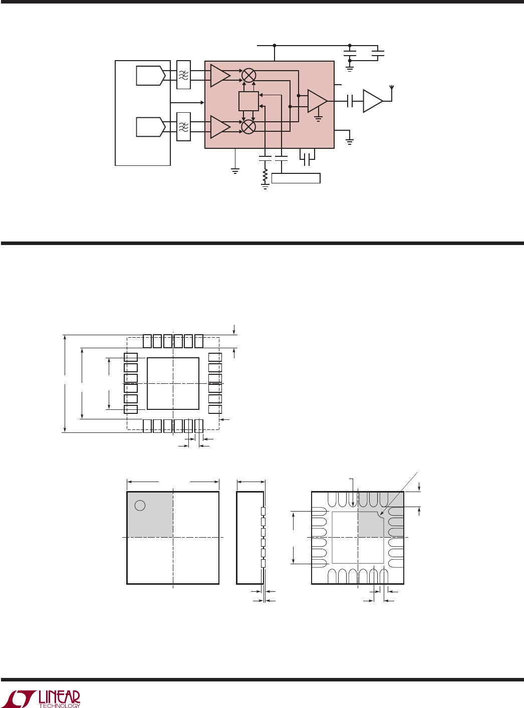
In Figure 7 the simplifi ed circuit schematic of the RF
output buffer is drawn. A plot of the RF port return loss vs
frequency is drawn in Figure 8 for EN = High and Low.
Enable Interface
Figure 9 shows a simplifi ed schematic of the EN pin
interface. The voltage necessary to turn on the LTC5598
is 2V. To disable (shut down) the chip, the enable voltage
must be below 1V. If the EN pin is not connected, the chip
is enabled. This EN = High condition is assured by the 125k
on-chip pull-up resistor. It is important that the voltage at
the EN pin does not exceed V
CC
by more than 0.3V. Should
APPLICATIONS INFORMATION
RF
1k
1.8V
4.6V
48Ω
48Ω
1k
1V
2.8V
FROM
INTERNAL
MIXERS
INTERNAL
BIAS
5598 F07
V
CC2
Figure 7. Simplifi ed Circuit Schematic of the RF Output
FREQUENCY (MHz)
1
RETURN LOSS (dB)
–10
–30
–20
–40
100 1000
10
–60
–50
0
5598 F08
EN = LOW
EN = HIGH
C6 = 220nF, SEE FIGURE 10
Figure 8. RF Port Return Loss vs Frequency
EN
V
CC1
125k
50k
2V
3V
INTERNAL
ENABLE
CIRCUIT
5598 F09
Figure 9: EN Pin Interface
LTC5598
14
5598f
APPLICATIONS INFORMATION
Figure 12. Bottom Side of Evaluation Board
Figure 11. Component Side of Evaluation Board
C8
470nF
C6
10nF
C7
10nF
C5
10nF
C3
1nF
R2
5.6Ω
R1
C4
4.7μF
C1
4.7μF
C2
1nF
EN
GND
LOP
LOM
GND
CAPA
1
2
3
4
5
6
18
17
16
15
14
13
7 8 9 10 11 12 25
24 23 22 21 20 19
V
CC2
GNDRF
RF
NC
GNDRF
NC
GND
GND
BBPI
BBMI
GND
V
CC1
CAPB
GND
BBMQ
BBPQ
GND
GND
GND
BBMQ
EN
BBPQ
RF OUT
U1
LTC5598
BOARD NUMBER: DC1455A
J6
J1
LOP
J3
LOM
J5
J7
J2
J4
GND
5598 F10
C10
2.2pF
C9
2.2pF
L1
3.3nH
L2
3.3nH
V
CC
BBMI
BBPI
Figure 10. Evaluation Circuit Schematic
this occur, the supply current could be sourced through
the EN pin ESD protection diodes, which are not designed
to carry the full supply current, and damage may result.
Evaluation Board
Figure 10 shows the evaluation board schematic. A good
ground connection is required for the exposed pad. If this
is not done properly, the RF performance will degrade.
Additionally, the exposed pad provides heat sinking for the
part and minimizes the possibility of the chip overheating.
Resistors R1 and R2 reduce the charging current in
capacitors C1 and C4 (see Figure 10) and will reduce
supply ringing during a fast power supply ramp-up in
case an inductive cable is connected to the V
CC
and GND
turrets. For EN = High, the voltage drop over R1 and R2
is about 0.15V. If a power supply is used that ramps up
slower than 10V/μs and limits the overshoot on the supply
below 5.6V, R1 and R2 can be omitted.
The LTC5598 can be used for base-station applications
with various modulation formats. Figure 13 shows a
typical application.
LTC5598
15
5598f
Information furnished by Linear Technology Corporation is believed to be accurate and reliable.
However, no responsibility is assumed for its use. Linear Technology Corporation makes no representa-
tion that the interconnection of its circuits as described herein will not infringe on existing patent rights.
PACKAGE DESCRIPTION
UF Package
24-Lead (4mm × 4mm) Plastic QFN
(Reference LTC DWG # 05-08-1697)
4.00 p 0.10
(4 SIDES)
NOTE:
1. DRAWING PROPOSED TO BE MADE A JEDEC PACKAGE OUTLINE MO-220 VARIATION (WGGD-X)—TO BE APPROVED
2. DRAWING NOT TO SCALE
3. ALL DIMENSIONS ARE IN MILLIMETERS
4. DIMENSIONS OF EXPOSED PAD ON BOTTOM OF PACKAGE DO NOT INCLUDE
MOLD FLASH. MOLD FLASH, IF PRESENT, SHALL NOT EXCEED 0.15mm ON ANY SIDE, IF PRESENT
5. EXPOSED PAD SHALL BE SOLDER PLATED
6. SHADED AREA IS ONLY A REFERENCE FOR PIN 1 LOCATION
ON THE TOP AND BOTTOM OF PACKAGE
PIN 1
TOP MARK
(NOTE 6)
0.40 p 0.10
2423
1
2
BOTTOM VIEW—EXPOSED PAD
2.45 p 0.10
(4-SIDES)
0.75 p 0.05
R = 0.115
TYP
0.25 p 0.05
0.50 BSC
0.200 REF
0.00 – 0.05
(UF24) QFN 0105
RECOMMENDED SOLDER PAD PITCH AND DIMENSIONS
0.70 p0.05
0.25 p0.05
0.50 BSC
2.45 p 0.05
(4 SIDES)
3.10 p 0.05
4.50 p 0.05
PACKAGE OUTLINE
PIN 1 NOTCH
R = 0.20 TYP OR
0.35 s 45o CHAMFER
Figure 13: 5MHz to 1600MHz Direct
Conversion Transmitter Application
90o
0o
LTC5598
NC
21
22
1
10
9
2, 5, 8, 11, 12,
19, 20, 23, 25
467
16
13, 15
14, 17
10nF
50Ω
3
18, 24
10nF 470nF
10nF
BASEBAND
GENERATOR
PA
RF = 5MHz
TO 1600MHz
1nF
x2
4.7μF
x2
EN
5V
V-I
V-I
I-CHANNEL
Q-CHANNEL
V
CC
5598 F13
I-DAC
Q-DAC
VCO/SYNTHESIZER
APPLICATIONS INFORMATION

LTC5598IUF#PBF

Mfr. #:
Manufacturer:
Analog Devices Inc.
Description:
Modulator / Demodulator 5MHz to 1600MHz Direct Quadrature Modulator
Lifecycle:
New from this manufacturer.
Delivery:
DHL FedEx Ups TNT EMS
Payment:
T/T Paypal Visa MoneyGram Western Union

Products related to this Datasheet