ZL30410 Data Sheet
24
Zarlink Semiconductor Inc.
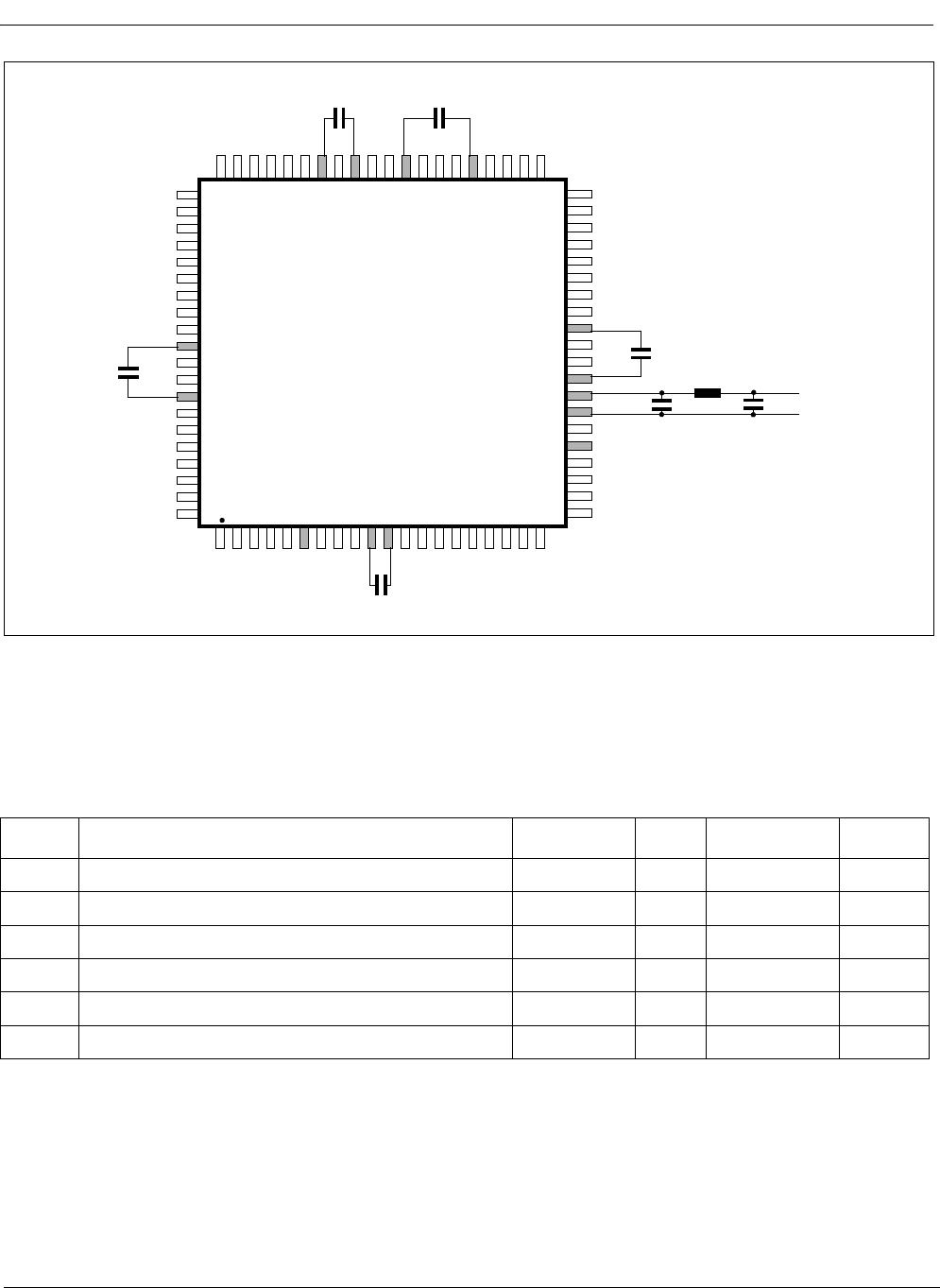
* Voltages are with respect to ground (GND) unless otherwise stated.
* Voltages are with respect to ground (GND) unless otherwise stated.
Note 1: VOS is defined as (V
OH
+ V
OL
) / 2.
Note 2: Rise and fall times are measured at 20% and 80% levels.
* Voltages are with respect to ground (GND) unless otherwise stated.
* Supply voltage and operating temperature are as per Recommended Operating Conditions.
* Timing for input and output signals is based on the worst case conditions (over T
A
and V
DD
).
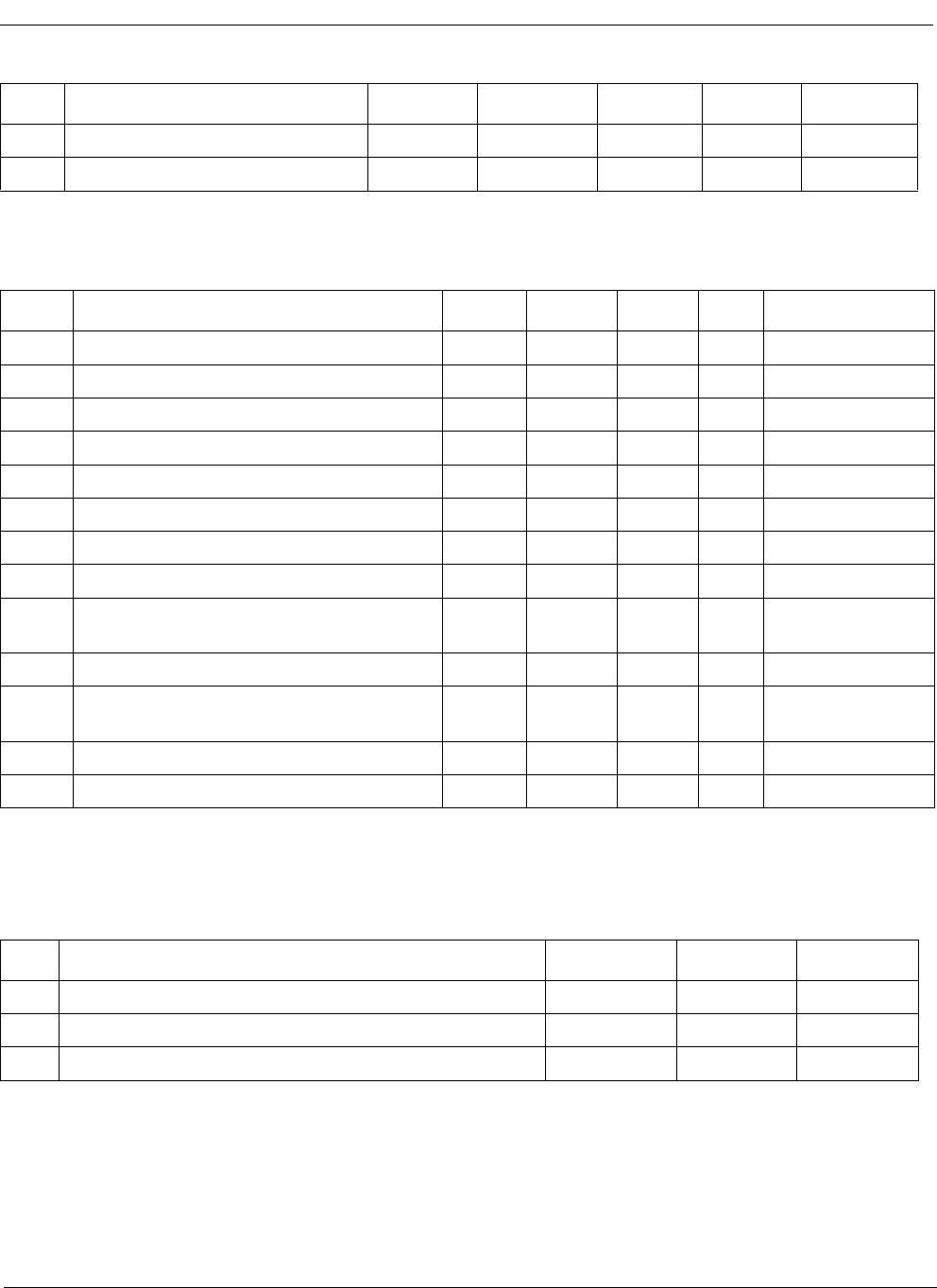
Recommended Operating Conditions*
Characteristics Symbol Min Typ Max Units
1 Supply voltage V
DD
3.0 3.3 3.6 V
2 Operating temperature T
A
-40 25 +85 °C
DC Electrical Characteristics*
Characteristics Symbol Min. Max. Units Notes
1 Supply current with C20i = 20MHz I
DD
155 mA Outputs unloaded
2 Supply current with C20i = 0V I
DDS
3.5 mA Outputs unloaded
3 CMOS high-level input voltage V
CIH
0.7 V
DD
V
4 CMOS low-level input voltage V
CIL
0.3V
DD
V
5 Input leakage current I
IL
15 µAV
I
=V
DD
or GND
6 High-level output voltage V
OH
2.4 V I
OH
=10mA
7 Low-level output voltage V
OL
0.4 V I
OL
=10 mA
8 LVDS: Differential output voltage V
OD
250 450 mV Z
T
= 100 Ω
9 LVDS: Change in VOD between
complementary output states
dV
OD
50 mV Z
T
= 100 Ω
10 LVDS: Offset voltage V
OS
1.125 1.375 V Note 1
11 LVDS: Change in VOS between
complementary output states
dV
OS
50 mV
12 LVDS: Output short circuit current I
OS
24 mA Pin short to GND
13 LVDS: Output rise and fall times T
RF
260 900 ps Note 2
AC Electrical Characteristics - Timing Parameter Measurement - CMOS Voltage Levels*
Characteristics Symbol Level Units
1 Threshold voltage V
T
0.5 V
DD
V
2 Rise and fall threshold voltage High V
HM
0.7 V
DD
V
3 Rise and fall threshold voltage Low V
LM
0.3 V
DD
V