ZL30410 Data Sheet
30
Zarlink Semiconductor Inc.
6.2 Performance Characteristics
* Supply voltage and operating temperature are as per Recommended Operating Conditions.
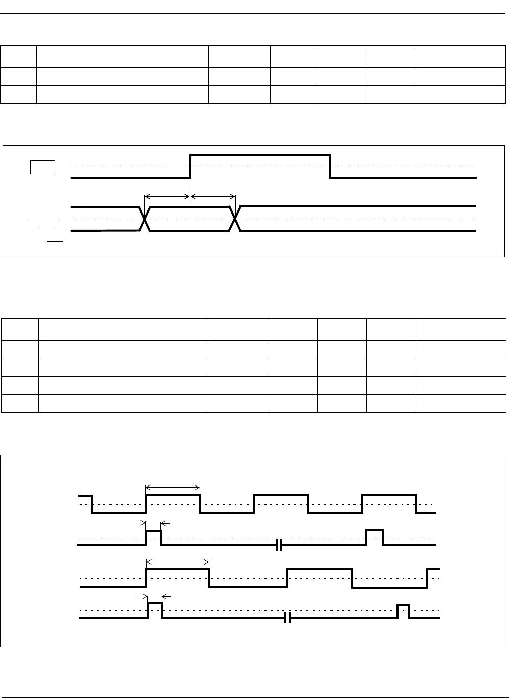
Performance Characteristics*
Characteristics Min. Typ. Max. Units Notes
1 Holdover accuracy (6 Hz filter) 70x10
-12
160x10
-12
Hz/Hz
2 Holdover accuracy (12 Hz filter) 140x10
-12
320x10
-12
Hz/Hz
3 Holdover stability NA Hz/Hz Holdover Stability is
determined by stability of
the 20 MHz Master Clock
oscillator
4 Capture range -104 +104 ppm The 20 MHz Master Clock
oscillator set at 0ppm
5 Reference Out of Range
Threshold
-12 +12 ppm The 20 MHz Master Clock
oscillator set at 0ppm
Lock Time
6 6 Hz or 12 Hz Filter 6 s ±4.6 ppm frequency offset
7 6 Hz or 12 Hz Filter 6 s ±20 ppm frequency offset
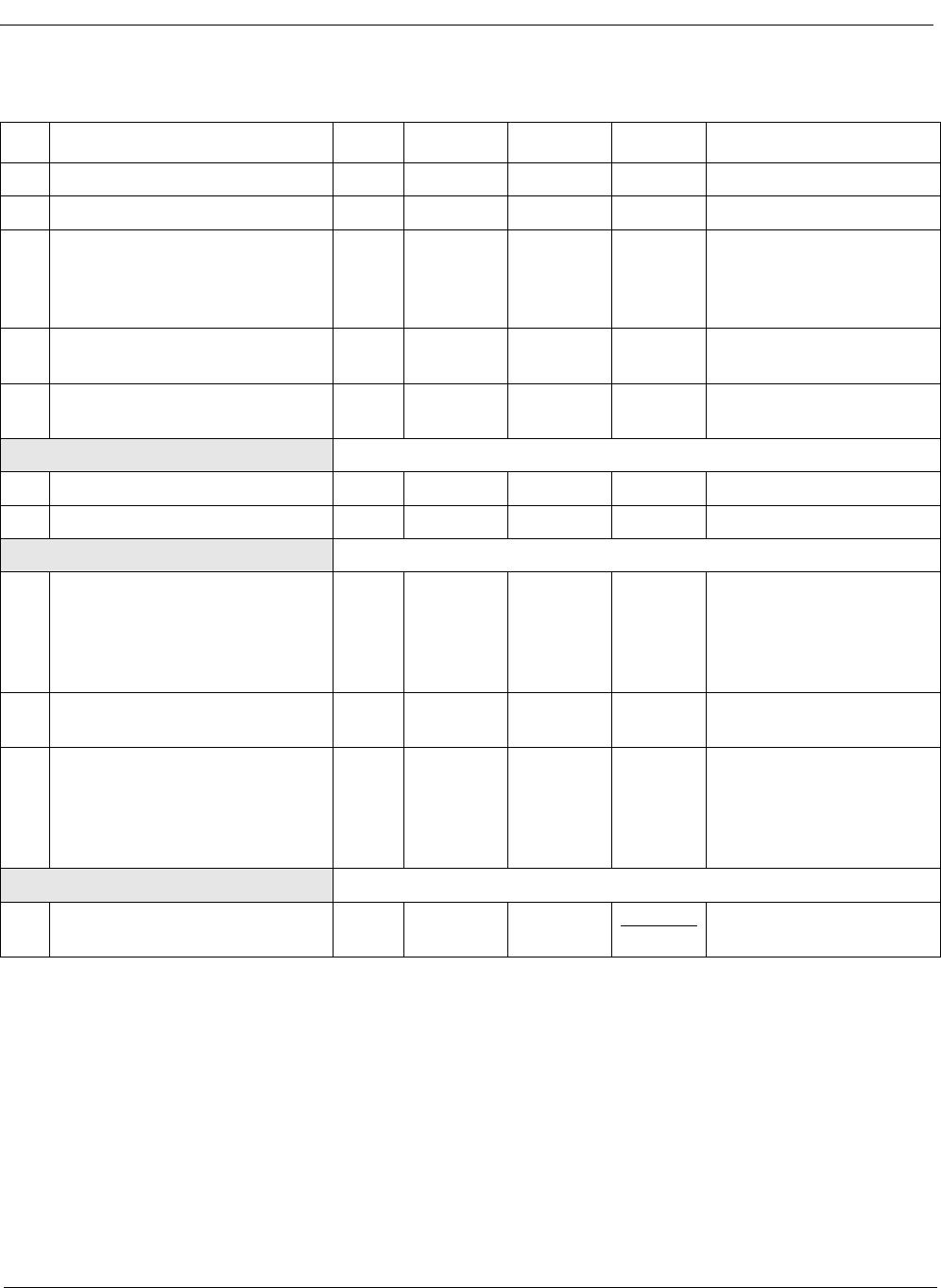
Output Phase Continuity (MTIE)
8 Reference switching:
PRI ⇒ SEC, SEC ⇒ PRI 50
5
ns
ns
PRI = SEC = 8 kHz
PRI or SEC = 1.544 MHz,
2.048 MHz, 19.44 MHz
9 Switching from Normal mode to
Holdover mode
0ns
10 Switching from Holdover mode
to Normal mode
50
2
ns
ns
PRI = SEC = 8 kHz
PRI or SEC = 1.544 MHz,
2.048 MHz, 19.44 MHz
Output Phase Slope
11 6 Hz Loop Filter 41 ns
1.326 ms