ADuM1240/ADuM1241/ADuM1245/ADuM1246 Data Sheet
Rev. B | Page 10 of 24
ABSOLUTE MAXIMUM RATINGS
T
A
= 25°C, unless otherwise noted.
Table 17.
Parameter Rating
Storage Temperature (T
ST
) Range −65°C to +150°C
Ambient Operating Temperature
(T
A
) Range
−40°C to +125°C
Supply Voltages (V
DD1
, V
DD2
) −0.5 V to +5 V
Input Voltages (V
IA
, V
IB
) −0.5 V to V
DDI
+ 0.5 V
Output Voltages (V
OA
, V
OB
)
−0.5 V to V
DD2
+ 0.5 V
Average Output Current per Pin
1
Side 1 (I
O1
) −10 mA to +10 mA
Side 2 (I
O2
) −10 mA to +10 mA
Common-Mode Transients
2
−100 kV/μs to +100 kV/μs
1
See Figure 4 for maximum rated current values for various temperatures.
2
Refers to common-mode transients across the insulation barrier. Common-
mode transients exceeding the absolute maximum ratings can cause
latch-up or permanent damage.
Stresses at or above those listed under Absolute Maximum
Ratings may cause permanent damage to the product. This is a
stress rating only; functional operation of the product at these
or any other conditions above those indicated in the operational
section of this specification is not implied. Operation beyond
the maximum operating conditions for extended periods may
affect product reliability.
CONTINUOUS WORKING VOLTAGE
Table 18. Maximum Continuous Working Voltage
1
Parameter Max Unit Constraint
AC Voltage
Bipolar Waveform 565 V peak 50-year minimum
lifetime
Unipolar Waveform 1131 V peak
50-year minimum
lifetime
DC Voltage 1131 V peak
50-year minimum
lifetime
1
Refers to continuous voltage magnitude imposed across the isolation
barrier. See the Insulation Lifetime section for more details.
ESD CAUTION
Data Sheet ADuM1240/ADuM1241/ADuM1245/ADuM1246
Rev. B | Page 11 of 24
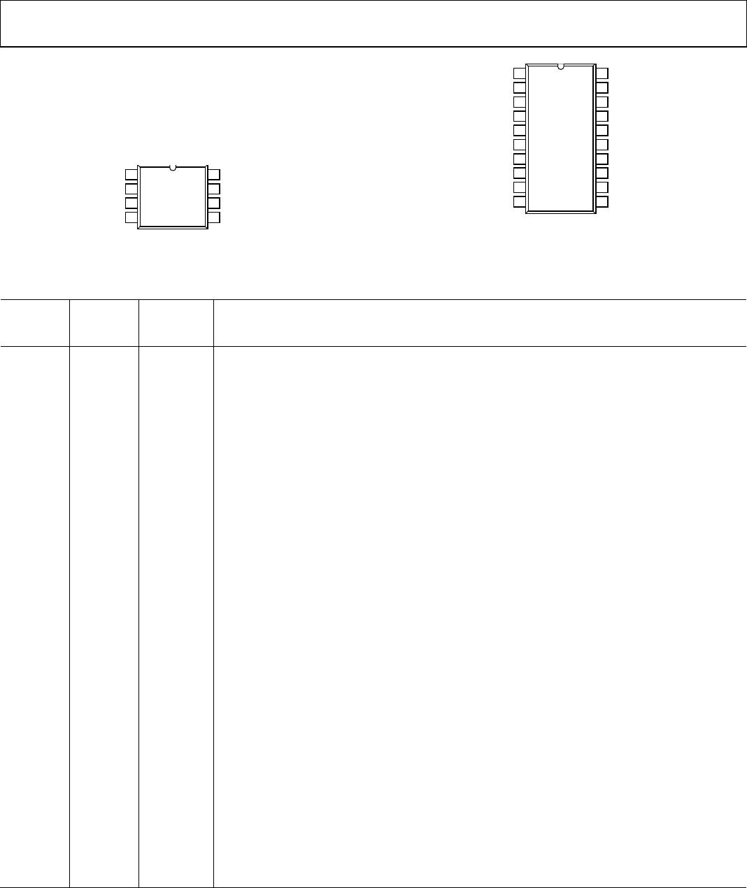
PIN CONFIGURATIONS AND FUNCTION DESCRIPTIONS
V
DD1
1
V
IA
2
V
IB
3
GND
1
4
V
DD2
8
7
6
GND
2
5
V
OA
V
OB
ADuM1240/
ADuM1245
TOP VIEW
(Not to Scale)
11925-104
Figure 5. ADuM1240/ADuM1245 8-Lead SOIC (R-8) Pin Configuration
V
DD1
1
GND
1
2
NIC
3
NIC
4
V
DD2
NIC = NOT INTERNALLY CONNECTED.
20
GND
2
19
NIC
18
NIC
17
V
IA
5
V
OA
16
V
IB
6
V
OB
15
EN
1
7
EN
2
14
NIC
8
NIC
13
NIC
9
NIC
12
GND
1
10
GND
2
11
ADuM1240/
ADuM1245
TOP VIEW
(Not to Scale)
11925-004
Figure 6. ADuM1240/ADuM1245 20-Lead SSOP (RS-20) Pin Configuration
Table 19. ADuM1240/ADuM1245 8-Lead SOIC (R-8) and 20-Lead SSOP (RS-20) Pin Function Descriptions
1
8-Lead
SOIC
Pin No.
2
20-Lead
SSOP
Pin No. Mnemonic Description
1 1 V
DD1
Supply Voltage for Isolator Side 1 (2.25 V to 3.6 V). Connect a ceramic bypass capacitor in the range
of 0.01 μF to 0.1 μF between V
DD1
and GND
1
.
N/A 2 GND
1
Ground 1. Ground reference for Isolator Side 1. Pin 2 and Pin 10 are internally connected, and
connecting both to GND
1
is recommended.
N/A 3 NIC Not Internally Connected. Leave this pin floating.
N/A 4 NIC Not Internally Connected. Leave this pin floating.
2 5 V
IA
Logic Input A.
3 6 V
IB
Logic Input B.
N/A 7 EN
1
Refresh and Watchdog Enable 1. In the 20-lead SSOP package, connecting Pin 7 to GND
1
enables
the input/output refresh and watchdog functionality for Side 1, supporting standard iCoupler
operation. Tying Pin 7 to V
DD1
disables the refresh and watchdog functionality for the lowest power
operation. See the DC Correctness and Low Power Operation section for a description of this mode.
EN
1
and EN
2
must be set to the same logic state.
N/A 8 NIC Not Internally Connected. Leave this pin floating.
N/A 9 NIC Not Internally Connected. Leave this pin floating.
4 10 GND
1
Ground 1. Ground reference for Isolator Side 1. In the 20-lead SSOP package, Pin 2 and Pin 10 are
internally connected, and connecting both to GND
1
is recommended.
5 11 GND
2
Ground 2. Ground reference for Isolator Side 2. In the 20-lead SSOP package, Pin 11 and Pin 19 are
internally connected, and connecting both to GND
2
is recommended.
N/A 12 NIC Not Internally Connected. Leave this pin floating.
N/A 13 NIC Not Internally Connected. Leave this pin floating.
N/A 14 EN
2
Refresh and Watchdog Enable 2. In the 20-lead SSOP package, connecting Pin 14 to GND
2
enables
the input/output refresh and watchdog functionality for Side 2, supporting standard iCoupler
operation. Tying Pin 14 to V
DD2
disables the refresh and watchdog functionality for lowest power
operation. See the DC Correctness and Low Power Operation section for a description of this mode.
EN1 and EN2 must be set to the same logic state.
6 15 V
OB
Logic Output B.
7 16 V
OA
Logic Output A.
N/A 17 NIC Not Internally Connected. Leave this pin floating.
N/A 18 NIC Not Internally Connected. Leave this pin floating.
N/A 19 GND
2
Ground 2. Ground reference for Isolator Side 2. In the 20-lead SSOP package, Pin 11 and Pin 19 are
internally connected, and connecting both to GND
2
is recommended.
8 20 V
DD2
Supply Voltage for Isolator Side 2 (2.25 V to 3.6 V). Connect a ceramic bypass capacitor in the range
of 0.01 μF to 0.1 μF between V
DD2
and GND
2
.
1
Reference AN-1109 for specific layout guidelines.
2
N/A means not applicable.
ADuM1240/ADuM1241/ADuM1245/ADuM1246 Data Sheet
Rev. B | Page 12 of 24
V
DD1
1
V
OA
2
V
IB
3
GND
1
4
V
DD2
8
7
6
GND
2
5
V
IA
V
OB
ADuM1241/
ADuM1246
TOP VIEW
(Not to Scale)
11925-105
Figure 7. ADuM1241/ADuM1246 8-Lead SOIC (R-8) Pin Configuration
V
DD1
1
GND
1
2
NIC
3
NIC
4
V
DD2
NIC = NOT INTERNALLY CONNECTED.
20
GND
2
19
NIC
18
NIC
17
V
OA
5
V
IA
16
V
IB
6
V
OB
15
EN
1
7
EN
2
14
NIC
8
NIC
13
NIC
9
NIC
12
GND
1
10
GND
2
11
ADuM1241/
ADuM1246
TOP VIEW
(Not to Scale)
11925-005
Figure 8. ADuM1241/ADuM1246 20-Lead SSOP (RS-20) Pin Configuration
Table 20. ADuM1241/ADuM1246 8-Lead SOIC (R-8) and 20-Lead SSOP (RS-20) Pin Function Descriptions
1
8-Lead
SOIC
Pin No.
2
20-Lead
SSOP
Pin No.
Mnemonic Description
1 1 V
DD1
Supply Voltage for Isolator Side 1 (2.25 V to 3.6 V). Connect a ceramic bypass capacitor in the range
of 0.01 µF to 0.1 µF between V
DD1
and GND
1
.
N/A 2 GND
1
Ground 1. Ground reference for Isolator Side 1. Pin 2 and Pin 10 are internally connected, and
connecting both to GND
1
is recommended.
N/A 3 NIC Not Internally Connected. Leave this pin floating.
N/A
4
NIC
Not Internally Connected. Leave this pin floating.
2 5 V
OA
Logic Output A.
3 6 V
IB
Logic Input B.
N/A 7 EN
1
Refresh and Watchdog Enable 1. In the 20-lead SSOP package, connecting Pin 7 to GND
1
enables
the input/output refresh and watchdog functionality for Side 1, supporting standard iCoupler
operation. Tying Pin 7 to V
DD1
disables the refresh and watchdog functionality for the lowest power
operation. See the DC Correctness and Low Power Operation section for a description of this mode.
EN
1
and EN
2
must be set to the same logic state.
N/A 8 NIC Not Internally Connected. Leave this pin floating.
N/A 9 NIC Not Internally Connected. Leave this pin floating.
4 10 GND
1
Ground 1. Ground reference for Isolator Side 1. In the 20-lead SSOP package, Pin 2 and Pin 10 are
internally connected, and connecting both to GND
1
is recommended.
5 11 GND
2
Ground 2. Ground reference for Isolator Side 2. In the 20-lead SSOP package, Pin 11 and Pin 19 are
internally connected, and connecting both to GND
2
is recommended.
N/A 12 NIC Not Internally Connected. Leave this pin floating.
N/A 13 NIC Not Internally Connected. Leave this pin floating.
N/A 14 EN
2
Refresh and Watchdog Enable 2. In the 20-lead SSOP package, connecting Pin 14 to GND
2
enables
the input/output refresh and watchdog functionality for Side 2, supporting standard iCoupler
operation. Tying Pin 14 to V
DD2
disables the refresh and watchdog functionality for lowest power
operation. See the DC Correctness and Low Power Operation section for a description of this mode.
EN1 and EN2 must be set to the same logic state.
6 15 V
OB
Logic Output B.
7 16 V
IA
Logic Input A.
N/A 17 NIC Not Internally Connected. Leave this pin floating.
N/A 18 NIC Not Internally Connected. Leave this pin floating.
N/A 19 GND
2
Ground 2. Ground reference for Isolator Side 2. In the 20-lead SSOP package, Pin 11 and Pin 19 are
internally connected, and connecting both to GND
2
is recommended.
8 20 V
DD2
Supply Voltage for Isolator Side 2 (2.25 V to 3.6 V). Connect a ceramic bypass capacitor in the range
of 0.01 µF to 0.1 µF between V
DD2
and GND
2
.
1
Reference AN-1109 for specific layout guidelines.
2
N/A means not applicable.

ADUM1240ARZ-RL7

Mfr. #:
Manufacturer:
Analog Devices Inc.
Description:
Digital Isolators DUAL-CHANNEL DI GITAL ISOLATORS
Lifecycle:
New from this manufacturer.
Delivery:
DHL FedEx Ups TNT EMS
Payment:
T/T Paypal Visa MoneyGram Western Union