Data Sheet ADuM1240/ADuM1241/ADuM1245/ADuM1246
Rev. B | Page 19 of 24
POWER CONSUMPTION
The supply current with refresh enabled at a given channel of
the ADuM1240/ADuM1241/ADuM1245/ADuM1246 isolators,
is a function of the supply voltage, the data rate of the channel,
and the output load of the channel.
For each input channel, the supply current is given by
I
DDI
= I
DDI (Q)
f ≤ 0.5 f
r
I
DDI
= I
DDI (D)
× (2f − f
r
) + I
DDI (Q)
f > 0.5 f
r
For each output channel, the supply current is given by
I
DDO
= I
DDO (Q)
f ≤ 0.5 f
r
I
DDO
= (I
DDO (D)
+ (0.5 × 10
−3
) × C
L
× V
DDO
) × (2f − f
r
) + I
DDO (Q)
f > 0.5 f
r
where:
I
DDI (D)
and I
DDO (D)
are the input and output dynamic supply
currents per channel (mA/Mbps).
C
L
is the output load capacitance (pF).
V
DDO
is the output supply voltage (V).
f is the input logic signal frequency (MHz); it is half the input
data rate, expressed in units of Mbps.
f
r
is the input stage refresh rate (Mbps) = 1/T
r
(µs).
I
DDI (Q)
and I
DDO (Q)
are the specified input and output quiescent
supply currents (mA).
To calculate the total V
DD1
and V
DD2
supply current, the supply
currents for each input and output channel corresponding to
V
DD1
and V
DD2
are calculated and totaled. Figure 9 through
Figure 16 show per channel supply currents as a function of
data rate for an unloaded output condition.
INSULATION LIFETIME
All insulation structures eventually degrade, when subjected to
voltage stress for a sufficiently long period. The rate of insulation
degradation is dependent on the characteristics of the voltage
waveform applied across the insulation. In addition to the testing
performed by the regulatory agencies, Analog Devices carries
out an extensive set of evaluations to determine the lifetime of
the insulation structure within the
ADuM1240/ADuM1241/ADuM1245/ADuM1246.
Analog Devices performs accelerated life testing using voltage levels
higher than the rated continuous working voltage. Acceleration
factors for several operating conditions are determined. These
factors allow calculation of the time to failure at the actual working
voltage.
The values shown in Table 18 summarize the peak voltage for 50
years of service life for a bipolar ac operating condition, and the
maximum CSA/VDE approved working voltages. In many cases,
the approved working voltage is higher than 50-year service life
voltage. Operation at these high working voltages can lead to
shortened insulation life, in some cases.
The insulation lifetime of the ADuM1240/ADuM1241/
ADuM1245/ADuM1246 depends on the voltage waveform type
imposed across the isolation barrier. The iCoupler insulation
structure degrades at different rates, depending on whether the
waveform is bipolar ac, unipolar ac, or dc. Figure 19, Figure 20,
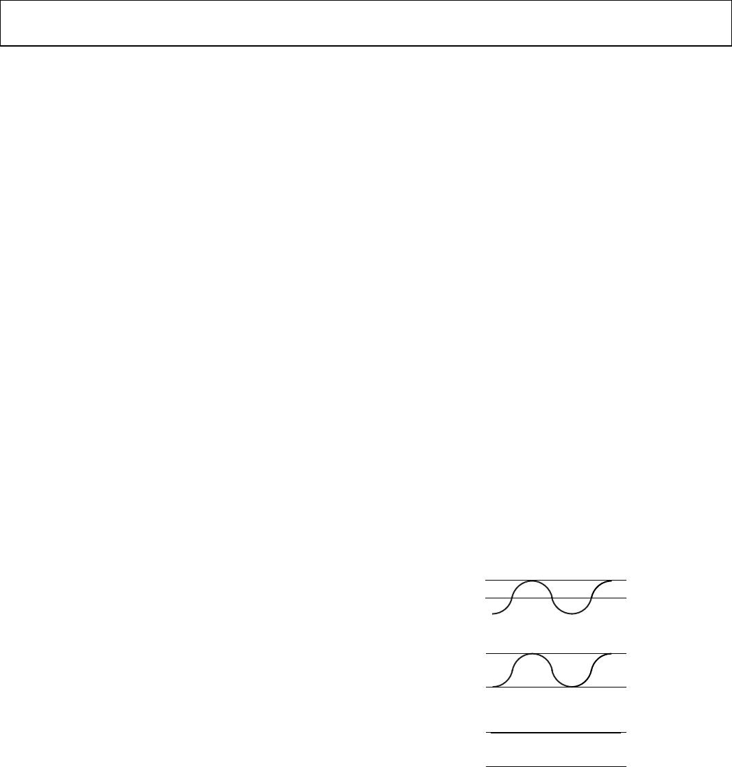
and Figure 21 illustrate these different isolation voltage waveforms.
Bipolar ac voltage is the most stringent environment. The goal
of a 50-year operating lifetime, under the ac bipolar condition,
determines the Analog Devices recommended maximum
working voltage.
In the case of unipolar ac or dc voltage, the stress on the insulation
is significantly lower. This allows operation at higher working
voltages, while still achieving a 50-year service life. The working
voltages listed in Table 18 can be applied while maintaining the 50-
year minimum lifetime, provided the voltages conform to either the
unipolar ac or dc voltage case. Treat any cross-insulation voltage
waveform that does not conform to Figure 33 or Figure 34 as a
bipolar ac waveform, and limit peak voltage to the 50-year lifetime
voltage value listed in Table 18.
Note that the voltage presented in Figure 33 is shown as sinusoidal
for illustration purposes only. It represents any voltage waveform
varying between 0 V and some limiting value. The limiting value
can be positive or negative, but the voltage must not cross 0 V.
0V
RATED PEAK VOLTAGE
11925-028
Figure 32. Bipolar AC Waveform
0V
RATED PEAK VOLTAGE
11925-029
Figure 33. Unipolar AC Waveform
0V
RATED PEAK VOLTAGE
1
1925-030
Figure 34. DC Waveform