AD7414/AD7415
Rev. F | Page 7 of 20
THEORY OF OPERATION
CIRCUIT INFORMATION
The AD7414/AD7415 are standalone digital temperature
sensors. The on-chip temperature sensor allows an accurate
measurement of the ambient device temperature to be made.
The 10-bit analog-to-digital converter converts the temperature
measured into a twos complement format for storage in the
temperature register. The ADC is made up of a conventional
successive-approximation converter based around a capacitor
digital-to-analog (DAC). The serial interface is I
2
C-and SMBus-
compatible. The AD7414/AD7415 require a 2.7 V to 5.5 V
power supply. The temperature sensor has a working
measurement range of −40°C to +125°C.
FUNCTIONAL DESCRIPTION
Temperature measurement is initiated by two methods. The
first uses an internal clock countdown of 800 ms, and a
conversion is performed. The internal oscillator is the only
circuit that is powered up between conversions, and once it
times out, every 800 ms, a wake-up signal is sent to power up
the rest of the circuitry. A monostable is activated at the
beginning of the wake-up signal to ensure that sufficient time is
given to the power-up process. The monostable typically takes
4 μs to time out. It then takes typically 25 μs for each conversion
to be completed. The new temperature value is loaded into the
temperature value register and ready for reading by the I
2
C
interface.
A temperature measurement is also initiated every time the
one-shot method is used. This method requires the user to
write to the one-shot bit in the configuration register when a
temperature measurement is needed. Setting the one-shot bit to
1 starts a temperature conversion directly after the write
operation. The track-and-hold goes into hold approximately
4 μs (monostable time out) after the STOP condition, and a
conversion is then initiated. Typically 25 μs later, the conversion
is complete and the temperature value register is loaded with a
new temperature value.
The measurement modes are compared with a high tempera-
ture limit, stored in an 8-bit read/write register. This is applica-
ble only to the AD7414, because the AD7415 does not have an
ALERT pin and subsequently does not have an overtemperature
monitoring function. If the measurement is greater than the
high limit, the ALERT pin is activated (if it has already been
enabled in the configuration register). There are two ways to
deactivate the ALERT pin again: when the alert reset bit in the
configuration register is set to 1 by a write operation, and when
the temperature measured is less than the value in the T
LOW
register. This ALERT pin is compatible with the SMBus
SMBALERT option.
Configuration functions consist of
• Switching between normal operation and full power-
down
• Enabling or disabling the SCL and SDA filters
• Enabling or disabling the ALERT function
• Setting the ALERT pin polarity
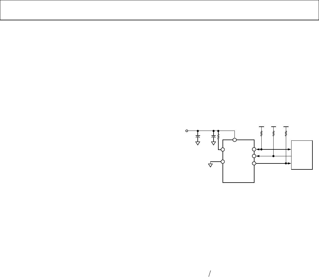
SUPPLY
2.7V TO
5.5V
10μF 1kΩ0.1μF
SDA
SCL
ALERT
AS
GND
AD7414
V
DD
02463-006
10kΩ 10kΩ 10kΩ
V
DD
V
DD
V
DD
μ
C/
μ
P
Figure 6. Typical Connection Diagram
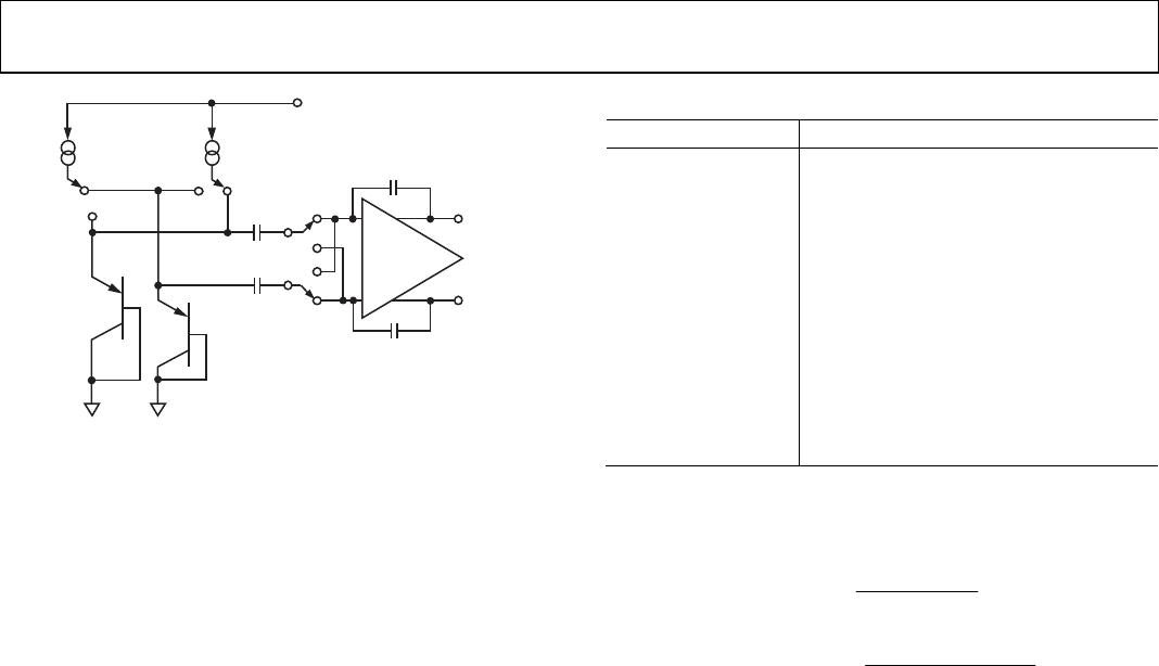
MEASUREMENT TECHNIQUE
A common method of measuring temperature is to exploit the
negative temperature coefficient of a diode, or the base-emitter
voltage of a transistor, operated at constant current.
Unfortunately, this technique requires calibration to null the
effect of the absolute value of V
BE
, which varies from device to
device. The technique used in the AD7414/AD7415 is to
measure the change in V
BE
when the device is operated at two
different currents. This is given by
)
NlnqKTV
BE
where:
K is Boltzmann’s constant.
q is the charge on the electron (1.6 × 10
–19
Coulombs).
T is the absolute temperature in Kelvins.
N is the ratio of the two currents.