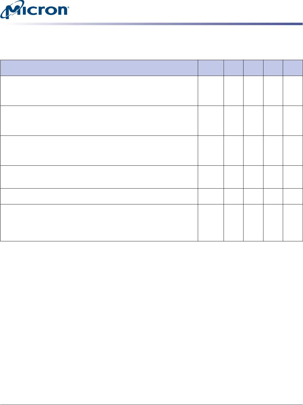
Table 11: DDR2 I
DD
Specifications and Conditions – 1GB (Die Revision M) (Continued)
Values shown for MT47H128M8 DDR2 SDRAM only and are computed from values specified in the 1Gb (128 Meg x 8) com-
ponent data sheet
Parameter Symbol -1GA
-80E/
-800 -667 Units
Active standby current: All device banks open;
t
CK =
t
CK (I
DD
),
t
RAS =
t
RAS
MAX (I
DD
),
t
RP =
t
RP (I
DD
); CKE is HIGH, S# is HIGH between valid commands;
Other control and address bus inputs are switching; Data bus inputs are switch-
ing
I
DD3N
320 264 240 mA
Operating burst write current: All device banks open; Continuous burst
writes; BL = 4, CL = CL (I
DD
), AL = 0;
t
CK =
t
CK (I
DD
),
t
RAS =
t
RAS MAX (I
DD
),
t
RP =
t
RP (I
DD
); CKE is HIGH, S# is HIGH between valid commands; Address bus inputs
are switching; Data bus inputs are switching
I
DD4W
1160 1000 920 mA
Operating burst read current: All device banks open; Continuous burst read,
I
OUT
= 0mA; BL = 4, CL = CL (I
DD
), AL = 0;
t
CK =
t
CK (I
DD
),
t
RAS =
t
RAS MAX (I
DD
),
t
RP =
t
RP (I
DD
); CKE is HIGH, S# is HIGH between valid commands; Address bus
inputs are switching; Data bus inputs are switching
I
DD4R
1120 960 880 mA
Burst refresh current:
t
CK =
t
CK (I
DD
); REFRESH command at every
t
RFC (I
DD
)
interval; CKE is HIGH, S# is HIGH between valid commands; Other control and
address bus inputs are switching; Data bus inputs are switching
I
DD5
1320 1240 1200 mA
Self refresh current: CK and CK# at 0V; CKE 0.2V; Other control and ad-
dress bus inputs are floating; Data bus inputs are floating
I
DD6
56 56 56 mA
Operating bank interleave read current: All device banks interleaving
reads; I
OUT
= 0mA; BL = 4, CL = CL (I
DD
), AL =
t
RCD (I
DD
) - 1 ×
t
CK (I
DD
);
t
CK =
t
CK
(I
DD
),
t
RC =
t
RC (I
DD
),
t
RRD =
t
RRD (I
DD
),
t
RCD =
t
RCD (I
DD
); CKE is HIGH, S# is
HIGH between valid commands; Address bus inputs are stable during deselects;
Data bus inputs are switching
I
DD7
1760 1680 1480 mA
1GB, 2GB (x64, SR) 200-Pin DDR2 SDRAM SODIMM
I
DD
Specifications
PDF: 09005aef83c2a451
htf8c128_256x64hz.pdf - Rev. E 4/14 EN
13
Micron Technology, Inc. reserves the right to change products or specifications without notice.
© 2009 Micron Technology, Inc. All rights reserved.
Table 12: DDR2 I
DD
Specifications and Conditions – 2GB (Die Revision C)
Values shown for MT47H256M8 DDR2 SDRAM only and are computed from values specified in the 2Gb (256 Meg x 8) com-
ponent data sheet
Parameter Symbol -1GA
-80E/
-800 -667 Units
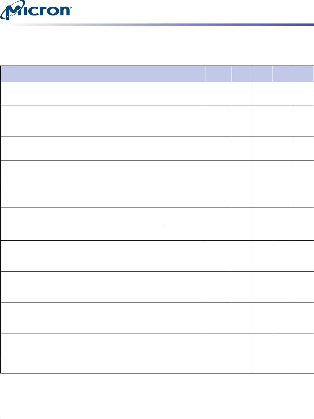
Operating one bank active-precharge current:
t
CK =
t
CK (I
DD
),
t
RC =
t
RC
(I
DD
),
t
RAS =
t
RAS MIN (I
DD
); CKE is HIGH, S# is HIGH between valid commands;
Address bus inputs are switching; Data bus inputs are switching
I
DD0
680 600 560 mA
Operating one bank active-read-precharge current: I
OUT
= 0mA; BL = 4, CL
= CL (I
DD
), AL = 0;
t
CK =
t
CK (I
DD
),
t
RC =
t
RC (I
DD
),
t
RAS =
t
RAS MIN (I
DD
),
t
RCD =
t
RCD (I
DD
); CKE is HIGH, S# is HIGH between valid commands; Address bus in-
puts are switching; Data pattern is same as I
DD4W
I
DD1
760 688 640 mA
Precharge power-down current: All device banks idle;
t
CK =
t
CK (I
DD
); CKE is
LOW; Other control and address bus inputs are stable; Data bus inputs are
floating
I
DD2P
96 96 96 mA
Precharge quiet standby current: All device banks idle;
t
CK =
t
CK (I
DD
); CKE
is HIGH, S# is HIGH; Other control and address bus inputs are stable; Data bus
inputs are floating
I
DD2Q
280 240 200 mA
Precharge standby current: All device banks idle;
t
CK =
t
CK (I
DD
); CKE is
HIGH, S# is HIGH; Other control and address bus inputs are switching; Data bus
inputs are switching
I
DD2N
320 280 240 mA
Active power-down current: All device banks open;
t
CK =
t
CK (I
DD
); CKE is LOW; Other control and address bus inputs are
stable; Data bus inputs are floating
Fast PDN exit
MR[12] = 0
I
DD3P
200 200 200 mA
Slow PDN exit
MR[12] = 1
112 112 112
Active standby current: All device banks open;
t
CK =
t
CK (I
DD
),
t
RAS =
t
RAS
MAX (I
DD
),
t
RP =
t
RP (I
DD
); CKE is HIGH, S# is HIGH between valid commands;
Other control and address bus inputs are switching; Data bus inputs are switch-
ing
I
DD3N
480 400 360 mA
Operating burst write current: All device banks open; Continuous burst
writes; BL = 4, CL = CL (I
DD
), AL = 0;
t
CK =
t
CK (I
DD
),
t
RAS =
t
RAS MAX (I
DD
),
t
RP =
t
RP (I
DD
); CKE is HIGH, S# is HIGH between valid commands; Address bus inputs
are switching; Data bus inputs are switching
I
DD4W
1280 1040 880 mA
Operating burst read current: All device banks open; Continuous burst read,
I
OUT
= 0mA; BL = 4, CL = CL (I
DD
), AL = 0;
t
CK =
t
CK (I
DD
),
t
RAS =
t
RAS MAX (I
DD
),
t
RP =
t
RP (I
DD
); CKE is HIGH, S# is HIGH between valid commands; Address bus
inputs are switching; Data bus inputs are switching
I
DD4R
1280 1040 880 mA
Burst refresh current:
t
CK =
t
CK (I
DD
); REFRESH command at every
t
RFC (I
DD
)
interval; CKE is HIGH, S# is HIGH between valid commands; Other control and
address bus inputs are switching; Data bus inputs are switching
I
DD5
1400 1360 1320 mA
Self refresh current: CK and CK# at 0V; CKE 0.2V; Other control and ad-
dress bus inputs are floating; Data bus inputs are floating
I
DD6
96 96 96 mA
1GB, 2GB (x64, SR) 200-Pin DDR2 SDRAM SODIMM
I
DD
Specifications
PDF: 09005aef83c2a451
htf8c128_256x64hz.pdf - Rev. E 4/14 EN
14
Micron Technology, Inc. reserves the right to change products or specifications without notice.
© 2009 Micron Technology, Inc. All rights reserved.
Table 12: DDR2 I
DD
Specifications and Conditions – 2GB (Die Revision C) (Continued)
Values shown for MT47H256M8 DDR2 SDRAM only and are computed from values specified in the 2Gb (256 Meg x 8) com-
ponent data sheet
Parameter Symbol -1GA
-80E/
-800 -667 Units
Operating bank interleave read current: All device banks interleaving
reads; I
OUT
= 0mA; BL = 4, CL = CL (I
DD
), AL =
t
RCD (I
DD
) - 1 ×
t
CK (I
DD
);
t
CK =
t
CK
(I
DD
),
t
RC =
t
RC (I
DD
),
t
RRD =
t
RRD (I
DD
),
t
RCD =
t
RCD (I
DD
); CKE is HIGH, S# is
HIGH between valid commands; Address bus inputs are stable during deselects;
Data bus inputs are switching
I
DD7
1840 1760 1600 mA
Serial Presence-Detect
For the latest SPD data, refer to Micron's SPD page: www.micron.com/SPD.
Table 13: SPD EEPROM Operating Conditions
Parameter/Condition Symbol Min Max Units
Supply voltage V
DDSPD
1.7 3.6 V
Input high voltage: logic 1; All inputs V
IH
V
DDSPD
× 0.7 V
DDSPD
+ 0.5 V
Input low voltage: logic 0; All inputs V
IL
–0.6 V
DDSPD
× 0.3 V
Output low voltage: I
OUT
= 3mA V
OL
0.4 V
Input leakage current: V
IN
= GND to V
DD
I
LI
0.1 3 µA
Output leakage current: V
OUT
= GND to V
DD
I
LO
0.05 3 µA
Standby current I
SB
1.6 4 µA
Power supply current, READ: SCL clock frequency = 100 kHz I
CCR
0.4 1 mA
Power supply current, WRITE: SCL clock frequency = 100 kHz I
CCW
2 3 mA
Table 14: SPD EEPROM AC Operating Conditions
Parameter/Condition Symbol Min Max Units Notes
SCL LOW to SDA data-out valid
t
AA 0.2 0.9 µs 1
Time bus must be free before a new transition can start
t
BUF 1.3 µs
Data-out hold time
t
DH 200 ns
SDA and SCL fall time
t
F 300 ns 2
SDA and SCL rise time
t
R 300 ns 2
Data-in hold time
t
HD:DAT 0 µs
Start condition hold time
t
HD:STA 0.6 µs
Clock HIGH period
t
HIGH 0.6 µs
Noise suppression time constant at SCL, SDA inputs
t
I 50 ns
Clock LOW period
t
LOW 1.3 µs
SCL clock frequency
t
SCL 400 kHz
Data-in setup time
t
SU:DAT 100 ns
1GB, 2GB (x64, SR) 200-Pin DDR2 SDRAM SODIMM
Serial Presence-Detect
PDF: 09005aef83c2a451
htf8c128_256x64hz.pdf - Rev. E 4/14 EN
15
Micron Technology, Inc. reserves the right to change products or specifications without notice.
© 2009 Micron Technology, Inc. All rights reserved.

MT8HTF25664HZ-800C1

Mfr. #:
Manufacturer:
Micron
Description:
Memory Modules DDR2 2GB SODIMM
Lifecycle:
New from this manufacturer.
Delivery:
DHL FedEx Ups TNT EMS
Payment:
T/T Paypal Visa MoneyGram Western Union