LTC2943
7
2943fa
For more information www.linear.com/LTC2943
BLOCK DIAGRAM
V
SUPPLY
COULOMB COUNTER
LTC2943
2943 BD
REFERENCE
GENERATOR
TEMPERATURE
SENSOR
ACCUMULATED
CHARGE
REGISTER
OSCILLATOR
F = 10kHz
CLK
I
2
C/
SMBUS
CC
AL ALCC
SCL
SDA
REF
CLKREF
+
REF
ADC
DATA AND
CONTROL
REGISTERS
MUX
SENSE
SENSE
+
GND
GND
GND
IN
7
8
2
3
1
6
4
5
LTC2943
8
2943fa
For more information www.linear.com/LTC2943
OPERATION
Overview
The LTC2943 is a battery gas gauge designed for use
with multicell batteries with terminal voltages from 3.6V
to 20V. It measures battery charge and discharge, battery
voltage, current and its own temperature.
A precision analog coulomb counter integrates current
through a sense resistor between the battery’s positive
terminal and the load or charger. Battery voltage, battery
current and silicon temperature are measured with an
internal ADC.
Coulomb Counter
Charge is the time integral of current. The LTC2943 mea-
sures charge
by monitoring the voltage developed across
a sense resistor. The differential voltage between SENSE
+
and SENSE
is applied to an auto-zeroed differential analog
integrator to infer charge.
When the integrator output ramps to REFHI or REFLO
levels, switches S1, S2, S3 and S4 toggle to reverse the
ramp direction (Figure 2). By observing the condition of
the switches and the ramp direction, polarity is determined.
This approach also significantly lowers the impact on offset
of the analog integrator as described in the Differential
Offset Voltage section.
A programmable prescaler effectively increases integration
time by a factor M programmable from 1 to 4096. At each
underflow or overflow of the prescaler, the accumulated
charge register (ACR) value is incremented
or decremented
one count. The value of accumulated charge is read via
the I
2
C interface.
Voltage, Current and Temperature ADC
The LTC2943 includes a 14-bit No Latency ΔΣ analog-to-
digital converter, with internal clock and voltage reference
circuits.
The ADC can be used to monitor the battery voltage at
SENSE
or the battery current flowing through the sense
resistor or to convert the output of the on-chip tempera-
ture sensor.
Conversion of voltage, current and temperature are trig-
gered by programming the control register via the I
2
C
interface. The LTC2943 includes a scan mode where
voltage, current and temperature conversion measure-
ments are executed every 10 seconds. At the end of each
conversion the corresponding registers are updated and
the converter goes to sleep to minimize quiescent current.
The temperature sensor generates a voltage proportional
to temperature with a slope of 2mV/K resulting in a volt-
age of 600mV at 27°C.
Power-Up Sequence
When SENSE
+
rises above a threshold of approximately
3.3V, the LTC2943 generates an internal power-on reset
(POR) signal and sets all registers to their default state.
In the default state, the coulomb counter is active while
the voltage, current and temperature ADC is switched
off.
The accumulated charge register is set to mid-scale
(7FFFh), all low threshold registers are set to 0000h and all
high threshold registers are set to FFFFh. The alert mode
is enabled and the coulomb counter prescaling factor M
is set to 4096.
2943 F02
REFHI
S1
V
CC
S2
S3
S4
REFLO
GND
SENSE
+
R
SENSE
I
BAT
BATTERY
+
LOADCHARGER
SENSE
1
8
2
M
PRESCALER
ACR
+
+
+
CONTROL
LOGIC
POLARITY
DETECTION
Figure 2. Coulomb Counter Section of the LTC2943
LTC2943
9
2943fa
For more information www.linear.com/LTC2943
Internal Registers
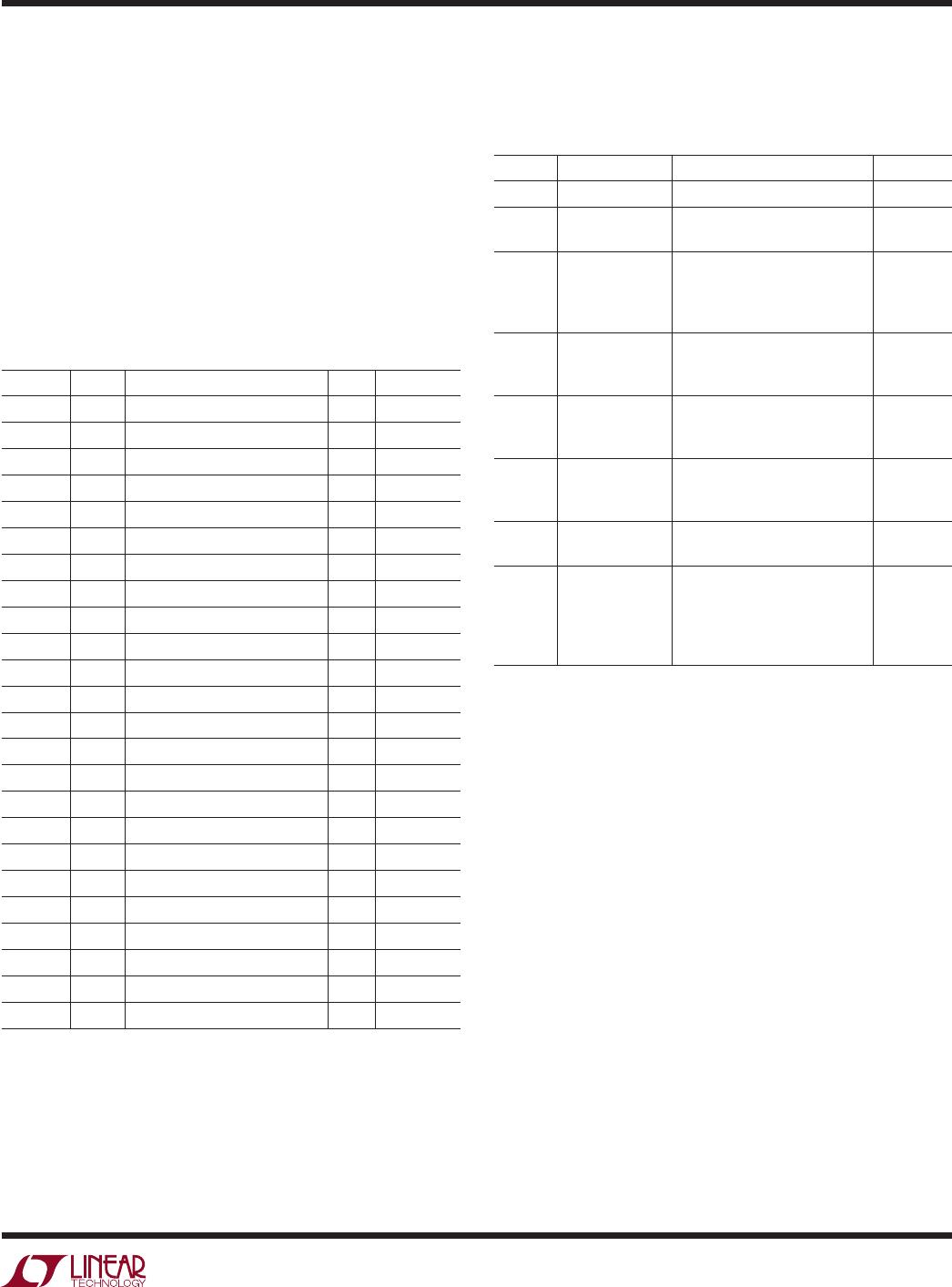
The LTC2943 register map is shown in Table 1. The
LTC2943 integrates current through a sense resistor,
measures battery voltage, current and temperature and
stores the results in internal 16-bit registers accessible
via I
2
C. High and low limits can be programmed for each
measured quantity. The LTC2943 continuously monitors
these limits and sets a flag in the status register when a
limit is exceeded. If the alert mode is enabled, the ALCC
pin pulls low.
Table 1. Register Map
ADDRESS NAME REGISTER DESCRIPTION R/W DEFAULT
00h A Status R See Table 2
01h B Control R/W 3Ch
02h C Accumulated Charge MSB R/W 7Fh
03h D Accumulated Charge LSB R/W FFh
04h E Charge Threshold High MSB R/W FFh
05h F Charge Threshold High LSB R/W FFh
06h G Charge Threshold Low MSB R/W 00h
07h H Charge Threshold Low LSB R/W 00h
08h I Voltage MSB R 00h
09h J Voltage LSB R 00h
0Ah K Voltage Threshold High MSB R/W FFh
0Bh L Voltage Threshold High LSB R/W FFh
0Ch M Voltage Threshold Low MSB R/W 00h
0Dh N Voltage Threshold Low LSB R/W 00h
0Eh O Current MSB R 00h
0Fh P Current LSB R 00h
10h Q Current Threshold High MSB R/W FFh
11h R Current Threshold High LSB R/W FFh
12h S Current Threshold Low MSB R/W 00h
13h T Current Threshold Low LSB R/W 00h
14h U Temperature MSB R 00h
15h V Temperature LSB R 00h
16h W Temperature Threshold High R/W FFh
17h X Temperature Threshold Low R/W 00h
R = Read, W = Write
APPLICATIONS INFORMATION
The status of the charge, voltage, current and temperature
alerts is reported in the status register shown in Table 2.
Table 2. Status Register (A)
BIT NAME OPERATION DEFAULT
A[7] Reserved
A[6] Current Alert
Indicates one of the current
limits was exceeded
0
A[5]
Accumulated
Charge
Overflow/
Underflow
Indicates that the value of the
ACR hit either top or bottom
0
A[4]
Temperature
Alert
Indicates one of the
temperature limits was
exceeded
0
A[3]
Charge Alert
High
Indicates that the ACR value
exceeded the charge threshold
high limit
0
A[2]
Charge Alert
Low
Indicates that the ACR value
exceeded the charge threshold
low limit
0
A[1] Voltage Alert
Indicates one of the voltage
limits was exceeded
0
A[0]
Undervoltage
Lockout Alert
Indicates recovery from
undervoltage. If set to 1, a
UVLO has occurred and the
contents of the registers are
uncertain
1
After each voltage, current or temperature conversion, the
conversion result is compared to the respective threshold
registers. If a value in the threshold registers is exceeded,
the corresponding bit A[6], A[4] or A[1] is set.
The accumulated charge register (ACR) is compared to
the charge thresholds every time the analog integrator
increments or decrements the prescaler. If the ACR value
exceeds the threshold register values, the corresponding
bit A[3] or A[2] are set. Bit A[5] is set if the accumulated
charge registers (ACR) overflows or underflows. At each
overflow or underflow, the ACR rolls over and resumes
integration.
The
undervoltage lockout (UVLO) bit of the status register
A[0] is set if, during operation, the voltage on the SENSE
+
pin drops below 3.5V without reaching the POR level. The
analog parts of the coulomb counter are switched off while
the digital register values are retained. After recovery of the
supply voltage the coulomb counter resumes integrating
with the stored value in the accumulated charge registers
but it has missed any charge flowing while SENSE
+
< 3.5V.

LTC2943IDD#TRPBF

Mfr. #:
Manufacturer:
Analog Devices / Linear Technology
Description:
Battery Management 20V Battery Gas Gauge with Voltage, Current & Temperature Measurement
Lifecycle:
New from this manufacturer.
Delivery:
DHL FedEx Ups TNT EMS
Payment:
T/T Paypal Visa MoneyGram Western Union

Products related to this Datasheet