Integrated Silicon Solution, Inc. - www.issi.com 7
Rev. A
10/22/09
IS42SM83200D / IS42SM16160D / IS42SM32800D
IS42RM83200D / IS42RM16160D / IS42RM32800D
PIN CONFIGURATIONS
90-ball TF-BGA for x32 (Top View) (8.00mm x 13.00mm Body, 0.8mm Ball Pitch)
1 2 3 4 5 6 7 8 9
A
B
C
D
E
F
G
H
J
K
L
M
N
P
R
DQ26
DQ28
VSSQ
VSSQ
VDDQ
VSS
A4
A7
CLK
DQM1
VDDQ
VSSQ
VSSQ
DQ11
DQ13
DQ24
VDDQ
DQ27
DQ29
DQ31
DQM3
A5
A8
CKE
NC
DQ8
DQ10
DQ12
VDDQ
DQ15
VSS
VSSQ
DQ25
DQ30
NC
A3
A6
NC
A9
NC
VSS
DQ9
DQ14
VSSQ
VSS
VDD
VDDQ
DQ22
DQ17
NC
A2
A10
NC
BA0
CAS
VDD
DQ6
DQ1
VDDQ
VDD
DQ23
VSSQ
DQ20
DQ18
DQ16
DQM2
A0
BA1
CS
WE
DQ7
DQ5
DQ3
VSSQ
DQ0
DQ21
DQ19
VDDQ
VDDQ
VSSQ
VDD
A1
A11
RAS
DQM0
VSSQ
VDDQ
VDDQ
DQ4
DQ2
PIN DESCRIPTIONS
8M x32 Pin Name
A0–A11 Row Address Input
A0–A8 Column Address Input
BA0, BA1 Bank Select Address
DQ0–DQ31 Data Input/Output
CLK System Clock Input
CKE Clock Enable
CS
Chip Select
RAS
Row Address Strobe Command
CAS
Column Address Strobe Command
8M x32 Pin Name
WE
Write Enable
DQM0 - DQM3 Data Input/Output Mask
VDD Power
VSS Ground
VDDQ Power Supply for I/O Pin
VSSQ Ground for I/O Pin
NC No Connection
8 Integrated Silicon Solution, Inc. - www.issi.com
Rev. A
10/22/09
IS42SM83200D / IS42SM16160D / IS42SM32800D
IS42RM83200D / IS42RM16160D / IS42RM32800D
Mobile SDRAM Functionality
ISSI’s 256Mb Mobile SDRAMs are pin compatible and have similar functionality with ISSI’s standard SDRAMs, but
offer lower operating voltages and power saving features. For detailed descriptions of pin functions, command truth
tables, functional truth tables, device operation as well as timing diagrams please refer to ISSI document “Mobile
Synchronous DRAM Device Operations & Timing Diagrams” listed at www.issi.com
REGISTER DEFINITION
Mode Register (MR) & Extended Mode Register (EMR)
There are two mode registers in the Mobile SDRAM; Mode Register (MR) and Extended Mode Register (EMR). The
Mode Register is discussed below, followed by the Extended Mode Register. The Mode Register is used to define
the specific mode of operation of the SDRAM. This definition includes the selection of burst length, a burst type, CAS
Latency, operating mode, and a write burst mode. The mode register is programmed via the LOAD MODE REGISTER
command and will retain the stored information until it is programmed again or the device loses power.
The EMR controls the functions beyond those controlled by the MR. These additional functions are special features
of the Mobile SDRAM. They include temperature-compensated self refresh (TCSR) control, partial-array self refresh
(PASR), and output drive strength. The EMR is programmed via the MODE REGISTER SET command with BA1
= 1 and BA0 = 0 and retains the stored information until it is programmed again or the device loses power. Not
programming the extended mode register upon initialization will result in default settings for the low-power features.
The extended mode will default with the temperature sensor enabled, full drive strength, and full array (all 4 banks)
refresh.
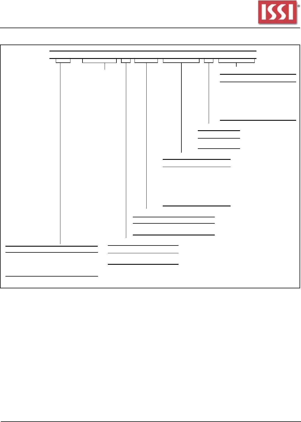
Mode Register Definition
The MR is used to define the specific mode of operation of the SDRAM. This definition includes the selection of a
burst length, a burst type, a CAS latency, an operating mode and a write burst mode, as shown in Figure MODE
REGISTER DEFINITION. The mode register is programmed via the LOAD MODE REGISTER command and will
retain the stored information until it is programmed again or the device loses power.
Mode register bits M0 - M2 specify the burst length, M3 specifies the type of burst (sequential or interleaved), M4 -
M6 specify the CAS latency, M7 and M8 specify the operating mode, M9 specifies the WRITE burst mode, and M10,
M11, and M12 are reserved for future use.
The mode register must be loaded when all banks are idle, and the controller must wait the specified time before
initiating the subsequent operation. Violating either of these requirements will result in unspecified operation.
Integrated Silicon Solution, Inc. - www.issi.com 9
Rev. A
10/22/09
IS42SM83200D / IS42SM16160D / IS42SM32800D
IS42RM83200D / IS42RM16160D / IS42RM32800D
Burst Length
Read and write accesses to the SDRAM are burst oriented, with the burst length being programmable, as shown in
MODE REGISTER DEFINITION. The burst length determines the maximum number of column locations that can
be accessed for a given READ or WRITE command. Burst lengths of 1, 2, 4 or 8 locations are available for both the
sequential and the interleaved burst types, and a full-page burst is available for the sequential type. The full-page burst
is used in conjunction with the BURST TERMINATE command to generate arbitrary burst lengths. Reserved states
should not be used, as unknown operation or incompatibility with future versions may result.
When a READ or WRITE command is issued, a block of columns equal to the burst length is effectively selected. All
accesses for that burst take place within this block, meaning that the burst will wrap within the block if a boundary is
reached. The block is uniquely selected by A1-A8 (x32), A1-A8 (x16) or A1-A9 (x8) when the burst length is set to two;
by A2-A8 (x32), A2-A8 (x16) or A2-A9 (x8) when the burst length is set to four; and by A3-A8 (x32), A3-A8 (x16) or
A3-A9 (x8) when the burst length is set to eight. The remaining (least significant) address bit(s) are used to select the
starting location within the block. Full-page bursts wrap within the page if the boundary is reached.
MODE REGISTER DEFINITION

IS42RM16160D-7BL

Mfr. #:
Manufacturer:
ISSI
Description:
DRAM 256M (16Mx16) 143MHz Mobile SDRAM, 2.5v
Lifecycle:
New from this manufacturer.
Delivery:
DHL FedEx Ups TNT EMS
Payment:
T/T Paypal Visa MoneyGram Western Union