NOVEMBER 4, 2016 5 4-OUTPUT CK420BQ DERIVATIVE
9SQL4954 DATASHEET
Absolute Maximum Ratings
Stresses above the ratings listed below can cause permanent damage to the 9SQL4954. These ratings, which are standard
values for IDT commercially rated parts, are stress ratings only. Functional operation of the device at these or any other
conditions above those indicated in the operational sections of the specifications is not implied. Exposure to absolute maximum
rating conditions for extended periods can affect product reliability. Electrical parameters are guaranteed only over the
recommended operating temperature range.
Electrical Characteristics–SMBus Parameters
PARAMETER SYMBOL CONDITIONS MIN TYP MAX UNITS NOTES
3.3V Supply Voltage VDDxxx Applies to all VDD pins -0.5 3.9 V 1,2
Input Voltage V
IN
-0.5
V
DD
+
0.5V
V1, 3
Input High Voltage, SMBus V
IHSMB
SMBus clock and data pins 3.9 V 1
Storage Temperature Ts -65 150 °C 1
Junction Temperature Tj 125 °C 1
Input ESD protection
ESD prot Human Body Model 2500 V
1
1
Guaranteed by desi
n and characterization, not 100% tested in production.
2
Operation under these conditions is neither implied nor guaranteed.
3
Not to exceed 4.5V.
TA = T
AMB;
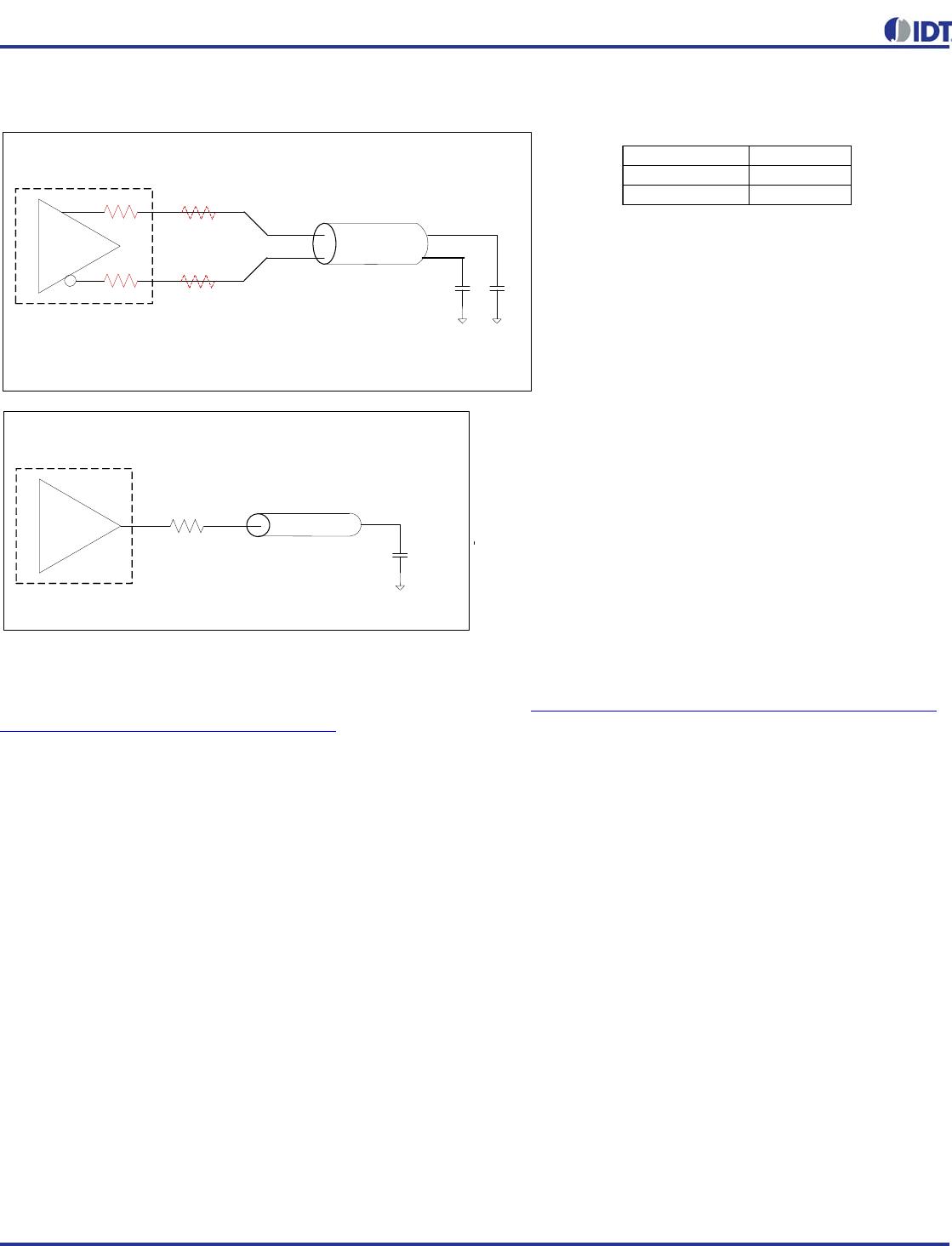
Supply Voltages per normal operation conditions, See Test Loads for Loading Conditions
PARAMETER SYMBOL CONDITIONS MIN TYP MAX UNITS NOTES
SMBus Input Low Voltage V
ILSMB
DDSMB
= 3.3V 0.8 V
SMBus Input High Voltage V
IHSMB
DDSMB
= 3.3V 2.1 3.6 V
SMBus Output Low Voltage V
OLSMB
PULLUP
0.4 V
SMBus Sink Current I
PULLUP
OL
4mA
Nominal Bus Voltage V
DDSMB
2.7 3.6 V
SCLK/SDATA Rise Time t
RSMB
(Max VIL - 0.15) to (Min VIH + 0.15) 1000 ns 1
SCLK/SDATA Fall Time t
FSMB
(Min VIH + 0.15) to (Max VIL - 0.15) 300 ns 1
SMBus Operating
Frequency
f
SMBMAX
Maximum SMBus operating frequency 500 kHz
1
Guaranteed by design and characterization, not 100% tested in production.