Applications Information
Output Matching to 50
Ω
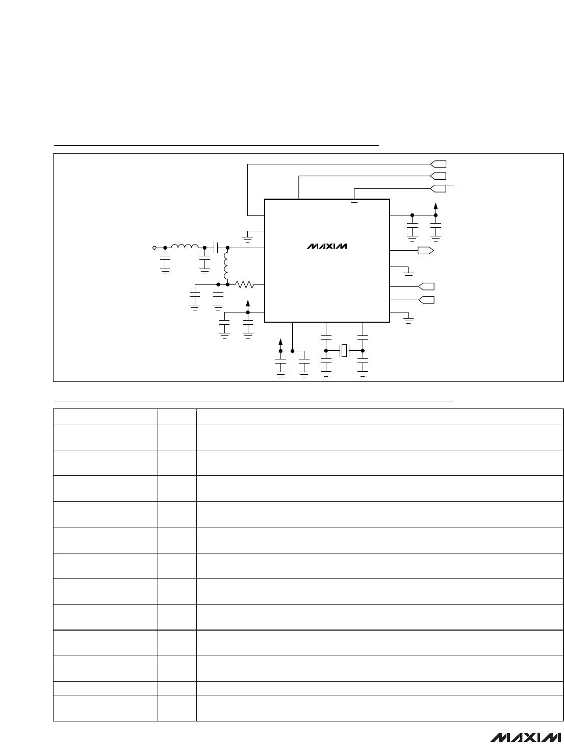
When matched to a 50Ω system, the MAX7057’s PA is
capable of delivering +9.2dBm of output power at
PAVDD = +2.7V with a broadband match. The output of
the PA is an open-drain transistor, which has internal
selectable shunt tuning capacitors (see the
Variable
Capacitor
section) for impedance matching. It is con-
nected to PAVDD or ROUT through a pullup inductor
for proper biasing. The internal selectable shunt capac-
itors make it easy for tuning when changing the output
frequency. The pullup inductor from the PA to PAVDD
or ROUT serves three main purposes: resonating the
capacitive PA output, providing biasing for the PA, and
acting as a high-frequency choke to prevent RF energy
from coupling onto the supply voltage. The pi network
between the PA output and the antenna also forms a
lowpass filter that provides attenuation for the higher-
order harmonics.
Output Matching to PCB Loop Antenna
In many applications, the MAX7057 must be imped-
ance-matched to a small-loop antenna. The antenna is
usually fabricated out of a copper trace on a PCB in a
rectangular, circular, or square pattern. The antenna
has an impedance that consists of a lossy component
and a radiative component. To achieve high radiating
efficiency, the radiative component should be as high
as possible, while minimizing the lossy component. In
addition, a loop antenna has an inherent loop induc-
tance associated with it (assuming the antenna is termi-
nated to ground). In a typical application, the
inductance of the loop antenna is approximately 50nH
to 100nH. The radiative and lossy impedances can be
anywhere from a few tenths of an ohm to 5Ω or 10Ω.
Layout Considerations
A properly designed PCB is an essential part of any
RF/microwave circuit. At high-frequency inputs and out-
puts, use controlled-impedance lines and keep them as
short as possible to minimize losses and radiation. At
high frequencies, trace lengths that are in the order of
λ/10 or longer act as antennas, where λ is the wave-
length.
Keeping the traces short also reduces parasitic induc-
tance. Generally, 1in of PCB trace adds about 20nH of
parasitic inductance. The parasitic inductance can
have a dramatic effect on the effective inductance of a
passive component. For example, a 0.5in trace con-
necting to a 100nH inductor adds an extra 10nH of
inductance, or 10%.
To reduce parasitic inductance, use wider traces and a
solid ground or power plane below the signal traces.
Using a solid ground plane can reduce the parasitic
inductance from approximately 20nH/in to 7nH/in. Also,
use low-inductance connections to the ground plane,
and place decoupling capacitors as close as possible
to all V
DD
pins.
MAX7057
300MHz to 450MHz Frequency-Programmable
ASK/FSK Transmitter
______________________________________________________________________________________ 17
ASK mode: Outputs flo[15:12].