LTC3555/LTC3555-X
1
3555fe
For more information www.linear.com/LTC3555
n
HDD-Based MP3 Players, PDAs, GPS, PMPs
n
Portable Medical Products
n
Handheld Instrumentation
n
Other USB-Based Handheld Products
FEATURES
APPLICATIONS
DESCRIPTION
High Efficiency USB Power
Manager + Triple
Step-Down DC/DC
The LT C
®
3555 family are highly integrated USB com-
patible power management and battery charger ICs for
Li-Ion/Polymer battery applications. They include a high
efficiency current limited switching PowerPath manager
with automatic load prioritization, a battery charger, an ideal
diode and three general purpose synchronous step-down
switching regulators.
The LTC3555 family limits input current to either 100mA
or 500mA for USB applications or 1A for adapter-powered
applications. Unlike linear chargers, the LTC3555 family’s
switching architecture transmits nearly all of the power
available from the USB port to the load with minimal loss
and heat which eases thermal constraints in small spaces.
Two of the three general purpose switching regulators can
provide up to 400mA and the third can deliver 1A. The
entire product can be controlled via I
2
C or simple I/O. The
LTC3555-1/LTC3555-3 versions offer “instant-on” power
delivery to the portable product even with a very low battery
voltage. The LTC3555-3 version also has a reduced charger
float voltage of 4.100V for battery safety and longevity.
The LTC3555 family is available in the low profile 28-pin
(4mm × 5mm × 0.75mm) QFN surface mount package.
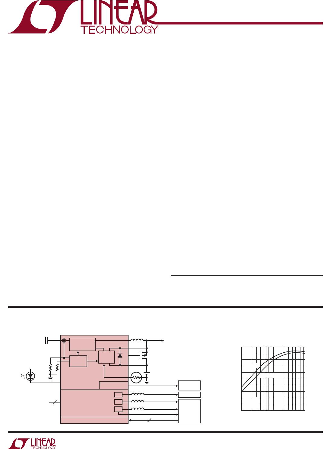
High Efficiency PowerPath Manager and Triple Step-Down Regulator
Power Manager
n
High Efficiency Switching PowerPath™ Controller
with Bat-Track™ Adaptive Output Control
n
Programmable USB or Wall Current Limit
(100mA/500mA/1A)
n
Full Featured Li-Ion/Polymer Battery Charger
n
1.5A Maximum Charge Current
n
Internal 180mΩ Ideal Diode + External Ideal Diode
Controller Powers Load in Battery Mode
n
Low No-Load Quiescent Current when Powered from
BAT (<32µA)
DC/DCs
n
Triple High Efficiency Step-Down DC/DCs
(1A/400mA/400mA I
OUT
)
n
All Regulators Operate at 2.25MHz
n
Dynamic Voltage Scaling on Two Outputs
n
I
2
C or Independent Enable, V
OUT
Controls
n
Low No-Load Quiescent Current: 20µA
n
28-Pin (4mm × 5mm × 0.75mm) QFN Package
Switching Regulator Efficiency to
System Load (P
OUT
/P
BUS
)
Li-Ion
0.8V TO 3.6V/400mA
3.3V/25mA
0.8V TO 3.6V/400mA
0.8V TO 3.6V/1A
RST
2
OPTIONAL
0V
T
TO OTHER
LOADS
+
LTC3555/LTC3555-X
TRIPLE
HIGH EFFICIENCY
STEP-DOWN
SWITCHING
REGULATORS
I
2
C PORT
ALWAYS ON LDO
MEMORY
RTC/LOW
POWER LOGIC
I
2
C
CORE
I/O
3555 TA01
µPROCESSOR
USB/WALL
4.35V TO 5.5V
CHARGE
ENABLE
CONTROLS
USB COMPLIANT
STEP-DOWN
REGULATOR
CC/CV
BATTERY
CHARGER
5
1
2
3
CURRENT
CONTROL
I
OUT
(A)
0.01
0
EFFICIENCY (%)
20
40
60
80
0.1 1
3555 TA01b
100
10
30
50
70
90
BAT = 4.2V
BAT = 3.3V
V
BUS
= 5V
I
BAT
= 0mA
10x MODE
TYPICAL APPLICATION
L, LT, LTC, LTM Linear Technology, the Linear logo and Burst Mode are registered trademarks
and PowerPath and Bat-Track are trademarks of Linear Technology Corporation. All other
trademarks are the property of their respective owners. Protected by U.S. Patents, including
6522118 and 6404251.
LTC3555/LTC3555-X
2
3555fe
For more information www.linear.com/LTC3555
ABSOLUTE MAXIMUM RATINGS
V
BUS
(Transient) t < 1ms,
Duty Cycle < 1% .......................................... 0.3V to 7V
V
IN1
, V
IN2
, V
IN3
, V
BUS
(Static), DV
CC
,
FB1, FB2, FB3, NTC, BAT, SCL, SDA,
RST3, CHRG ................................................. 0.3V to 6V
EN1, EN2, EN3 ................................ –0.3V to V
OUT
+0.3V
I
LIM0
, I
LIM1
...................0.3V to MAX (V
BUS
, V
OUT
BAT)
I
CLPROG
....................................................................3mA
I
RST3
, I
CHRG
............................................................50mA
I
PROG
........................................................................2mA
I
LDO3V3
...................................................................30mA
I
SW1
, I
SW2
........................................................... 600mA
I
SW
, I
SW3
, I
BAT
, I
VOUT
..................................................2A
Junction Temperature ........................................... 125°C
Operating Temperature Range (Note 2)....40°C to 85°C
Storage Temperature Range .................. 65°C to 125°C
(Notes 1, 2, 3)
SYMBOL PARAMETER CONDITIONS MIN TYP MAX UNITS
PowerPath Switching Regulator
V
BUS
Input Supply Voltage 4.35 5.5 V
I
BUSLIM
Total Input Current 1x Mode, V
OUT
= BAT
5x Mode, V
OUT
= BAT
10x Mode, V
OUT
= BAT
Suspend Mode, V
OUT
= BAT
l
l
l
l
87
436
800
0.31
95
460
860
0.38
100
500
1000
0.50
mA
mA
mA
mA
I
VBUSQ
V
BUS
Quiescent Current 1x Mode, I
OUT
= 0mA
5x Mode, I
OUT
= 0mA
10x Mode, I
OUT
= 0mA
Suspend Mode, I
OUT
= 0mA
7
15
15
0.044
mA
mA
mA
mA
9 10
TOP VIEW
29
UFD PACKAGE
28-LEAD (4mm × 5mm) PLASTIC QFN
11 12 13
28 27 26 25 24
14
23
6
5
4
3
2
1
LDO3V3
CLPROG
NTC
FB2
V
IN2
SW2
EN2
DV
CC
GATE
CHRG
PROG
FB1
V
IN1
SW1
EN1
RST3
I
LIM1
I
LIM0
SW
V
BUS
V
OUT
BAT
SCL
SDA
V
IN3
SW3
EN3
FB3
7
17
18
19
20
21
22
16
8
15
T
JMAX
= 125°C, θ
JA
= 37°C/W
EXPOSED PAD (PIN 29) IS GND, MUST BE SOLDERED TO PCB
The l denotes the specifications which apply over the full operating
temperature range, otherwise specifications are at T
A
= 25°C. V
BUS
= 5V, BAT = 3.8V, DV
CC
= 3.3V, R
PROG
= 1k, R
CLPROG
= 3k,
unless otherwise noted.
PIN CONFIGURATION
LEAD FREE FINISH TAPE AND REEL PART MARKING* PACKAGE DESCRIPTION TEMPERATURE RANGE
LTC3555EUFD#PBF LTC3555EUFD#TRPBF 3555 28-Lead (4mm x 5mm) Plastic QFN –40°C to 85°C
LTC3555IUFD#PBF LTC3555IUFD#TRPBF 3555 28-Lead (4mm x 5mm) Plastic QFN –40°C to 85°C
LTC3555EUFD-1#PBF LTC3555EUFD-1#TRPBF 35551 28-Lead (4mm x 5mm) Plastic QFN –40°C to 85°C
LTC3555IUFD-1#PBF LTC3555IUFD-1#TRPBF 35551 28-Lead (4mm x 5mm) Plastic QFN –40°C to 85°C
LTC3555EUFD-3#PBF LTC3555EUFD-3#TRPBF 35553 28-Lead (4mm x 5mm) Plastic QFN –40°C to 85°C
LTC3555IUFD-3#PBF LTC3555IUFD-3#TRPBF 35553 28-Lead (4mm x 5mm) Plastic QFN –40°C to 85°C
Consult LTC Marketing for parts specified with wider operating temperature ranges. *The temperature grade is identified by a label on the shipping container.
For more information on lead free part marking, go to: http://www.linear.com/leadfree/
For more information on tape and reel specifications, go to: http://www.linear.com/tapeandreel/. Some packages are available in 500 unit reels through
designated sales channels with #TRMPBF suffix.
ORDER INFORMATION
ELECTRICAL CHARACTERISTICS
http://www.linear.com/product/LTC3555#orderinfo
LTC3555/LTC3555-X
3
3555fe
For more information www.linear.com/LTC3555
SYMBOL PARAMETER CONDITIONS MIN TYP MAX UNITS
h
CLPROG
(Note 4)
Ratio of Measured V
BUS
Current to
CLPROG Program Current
1x Mode
5x Mode
10x Mode
Suspend Mode
224
1133
2140
11.3
mA/mA
mA/mA
mA/mA
mA/mA
I
OUT(POWERPATH)
V
OUT
Current Available Before
Loading BAT
1x Mode, BAT = 3.3V
5x Mode, BAT = 3.3V
10x Mode, BAT = 3.3V
Suspend Mode
135
672
1251
0.32
mA
mA
mA
mA
V
CLPROG
CLPROG Servo Voltage in Current
Limit
1x, 5x, 10x Modes
Suspend Mode
1.188
100
V
mV
V
UVLO_VBUS
V
BUS
Undervoltage Lockout Rising Threshold
Falling Threshold
3.95
4.30
4.00
4.35 V
V
V
UVLO_VBUS-BAT
V
BUS
to BAT Differential Undervoltage
Lockout
Rising Threshold
Falling Threshold
200
50
mV
mV
V
OUT
V
OUT
Voltage 1x, 5x, 10x Modes, 0V < BAT < 4.2V,
I
OUT
= 0mA, Battery Charger Off
3.4 BAT + 0.3 4.7 V
USB Suspend Mode, I
VOUT
= 250µA 4.5 4.6 4.7 V
f
OSC
Switching Frequency 1.8 2.25 2.7 MHz
R
PMOS_POWERPATH
PMOS On Resistance 0.18 Ω
R
NMOS_POWERPATH
NMOS On Resistance 0.30 Ω
I
PEAK_POWERPATH
Peak Switch Current Limit 1x, 5x Modes
10x
2
3
A
A
Battery Charger
V
FLOAT
BAT Regulated Output Voltage LTC3555/LTC3555-1
LTC3555/LTC3555-1
LTC3555-3
LTC3555-3
l
l
4.179
4.165
4.079
4.065
4.200
4.200
4.100
4.100
4.221
4.235
4.121
4.135
V
V
V
V
I
CHG
Constant Current Mode Charge
Current
R
PROG
= 1k
R
PROG
= 5k
980
185
1022
204
1065
223
mA
mA
I
BAT
Battery Drain Current V
BUS
> V
UVLO
, Battery Charger Off, I
VOUT
= 0µA
V
BUS
= 0V, I
VOUT
= 0µA (Ideal Diode Mode)
LTC3555
LTC3555-1/LTC3555-3
2 3.5
27
32
5
38
44
µA
µA
µA
V
PROG
PROG Pin Servo Voltage 1.000 V
V
PROG_TRKL
PROG Pin Servo Voltage in Trickle
Charge
BAT < V
TRKL
0.100 V
V
C/10
C/10 Threshold Voltage at PROG 100 mV
h
PROG
Ratio of I
BAT
to PROG Pin Current 1022 mA/mA
I
TRKL
Trickle Charge Current BAT < V
TRKL
100 mA
V
TRKL
Trickle Charge Threshold Voltage BAT Rising 2.7 2.85 3.0 V
ΔV
TRKL
Trickle Charge Hysteresis Voltage 135 mV
ΔV
RECHRG
Recharge Battery Threshold Voltage Threshold Voltage Relative to V
FLOAT
–75 –100 –125 mV
t
TERM
Safety Timer Termination Timer Starts when BAT = V
FLOAT
3.3 4 5 Hour
t
BADBAT
Bad Battery Termination Time BAT < V
TRKL
0.42 0.5 0.63 Hour
h
C/10
End of Charge Indication Current Ratio (Note 5) 0.088 0.1 0.112 mA/mA
ELECTRICAL CHARACTERISTICS
The l denotes the specifications which apply over the full operating
temperature range, otherwise specifications are at T
A
= 25°C. V
BUS
= 5V, BAT = 3.8V, DV
CC
= 3.3V, R
PROG
= 1k, R
CLPROG
= 3k,
unless otherwise noted.

LTC3555IUFD#TRPBF

Mfr. #:
Manufacturer:
Analog Devices / Linear Technology
Description:
Battery Management Hi Eff USB Pwr Manager + 3x Buck DC/DC
Lifecycle:
New from this manufacturer.
Delivery:
DHL FedEx Ups TNT EMS
Payment:
T/T Paypal Visa MoneyGram Western Union