LTC4071
1
4071fc
Typical applicaTion
DescripTion
Li-Ion/Polymer Shunt
Battery Charger System with
Low Battery Disconnect
The LTC
®
4071 allows simple charging of Li-Ion/Polymer
batteries from very low current, intermittent or continuous
charging sources. A near-zero current low battery latch-
ing disconnect function protects even the lowest capacity
batteries from deep discharge and potentially irreparable
damage. The 550nA to 50mA operating current makes
charging possible from previously unusable sources. With
its low operating current the LTC4071 is well suited to
charge low capacity Li-Ion or thin film batteries in energy
harvesting applications. The unique architecture of the
LTC4071 allows for an extremely simple battery charger
solution, requiring just one external resistor.
The LTC4071 offers a pin selectable float voltage with ±1%
accuracy. The integrated thermal battery qualifier extends
battery lifetime and improves reliability by automatically
reducing the battery float voltage at NTC thermistor tem-
peratures above 40°C. The LTC4071 also provides two
pin selectable low battery disconnect levels and a high
battery status output.
The device is offered in two thermally enhanced packages,
a compact low profile (0.75mm) 8-lead (2mm × 3mm)
DFN and an 8-lead MSOP package.
L, LT, LTC, LTM, Linear Technology, the Linear logo and Burst Mode are registered trademarks
and ThinSOT is a trademark of Linear Technology Corporation. All other trademarks are the
property of their respective owners.
FeaTures
applicaTions
n
Charger Plus Pack Protection in One IC
n
Low Operating Current (550nA)
n
Near Zero Current (<0.1nA) Low Battery Disconnect
Function to Protect Batteries from Over-Discharge
n
Pin Selectable Low Battery Disconnect Level:
2.7V or 3.2V
n
1% Float Voltage Accuracy Over Temperature
n
50mA Maximum Internal Shunt Current
n
Pin Selectable Float Voltage Options: 4.0V, 4.1V, 4.2V
n
Ultralow Power Pulsed NTC Float Conditioning for
Li-Ion/Polymer Protection
n
Suitable for Intermittent, Continuous and Very Low
Power Charging Sources
n
High Battery Status Output
n
Thermally Enhanced, Low Profile (0.75mm)
8-Lead (2mm × 3mm) DFN and MSOP Packages
n
Low Capacity, Li-Ion/Polymer Battery Back-Up
n
Thin Film Batteries
n
Energy Scavenging/Harvesting
n
Solar Power Systems with Back-Up
n
Memory Back-Up
n
Embedded Automotive
4071 TA01a
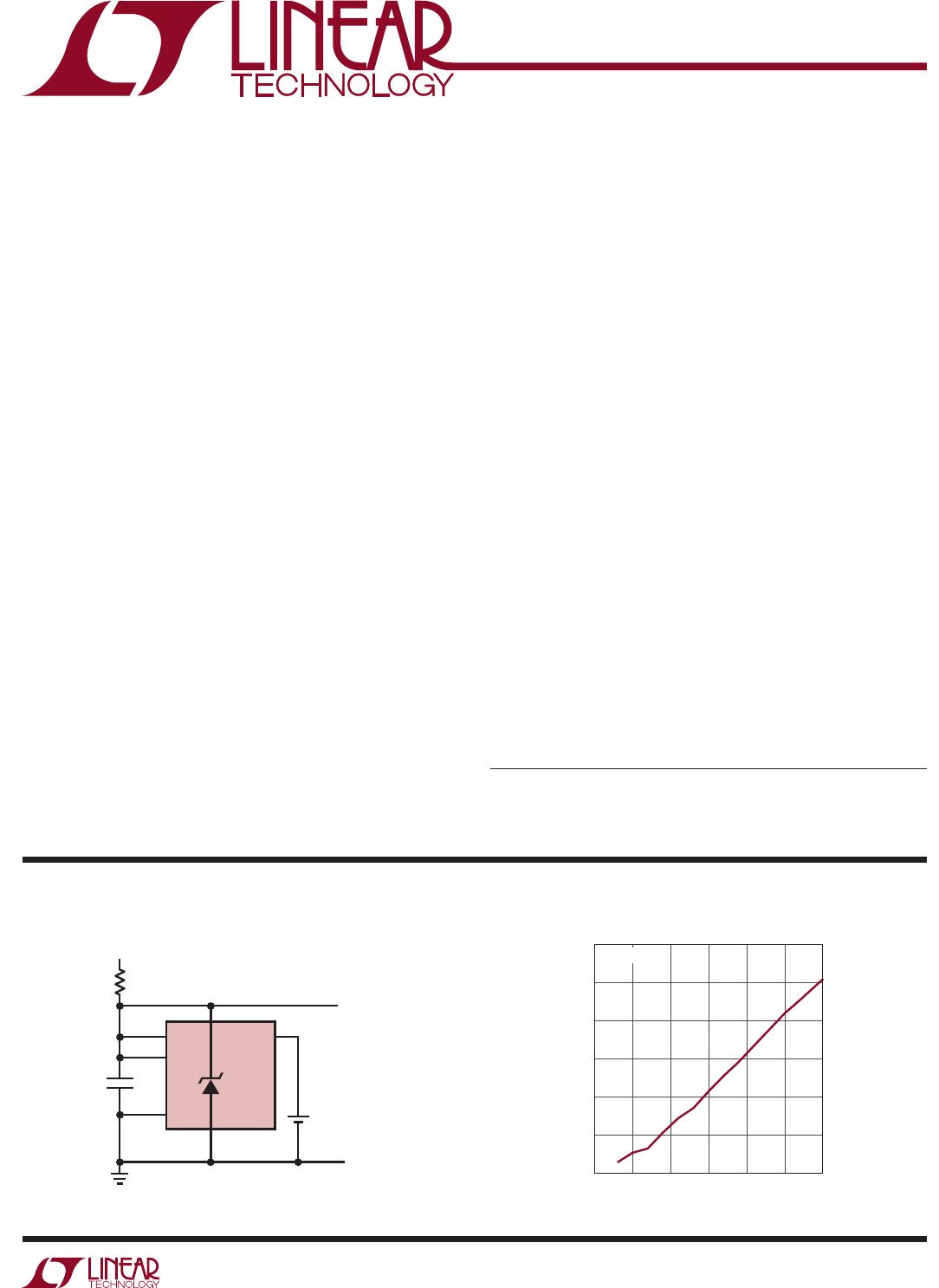
LTC4071
ADJ BAT
R
IN
GND
Li-Ion
NTC
V
CC
V
IN
LBSEL
+
TO SYSTEM LOAD: V
CC
1µF
TEMPERATURE (°C)
–25 0
I
LEAK
(A)
10p
125
4071 TA01b
1p
0.1p
5025 75 100
1n
100p
10n
100n
V
BAT
= 2.65V
Battery Disconnect I
LEAK
vs Temperature