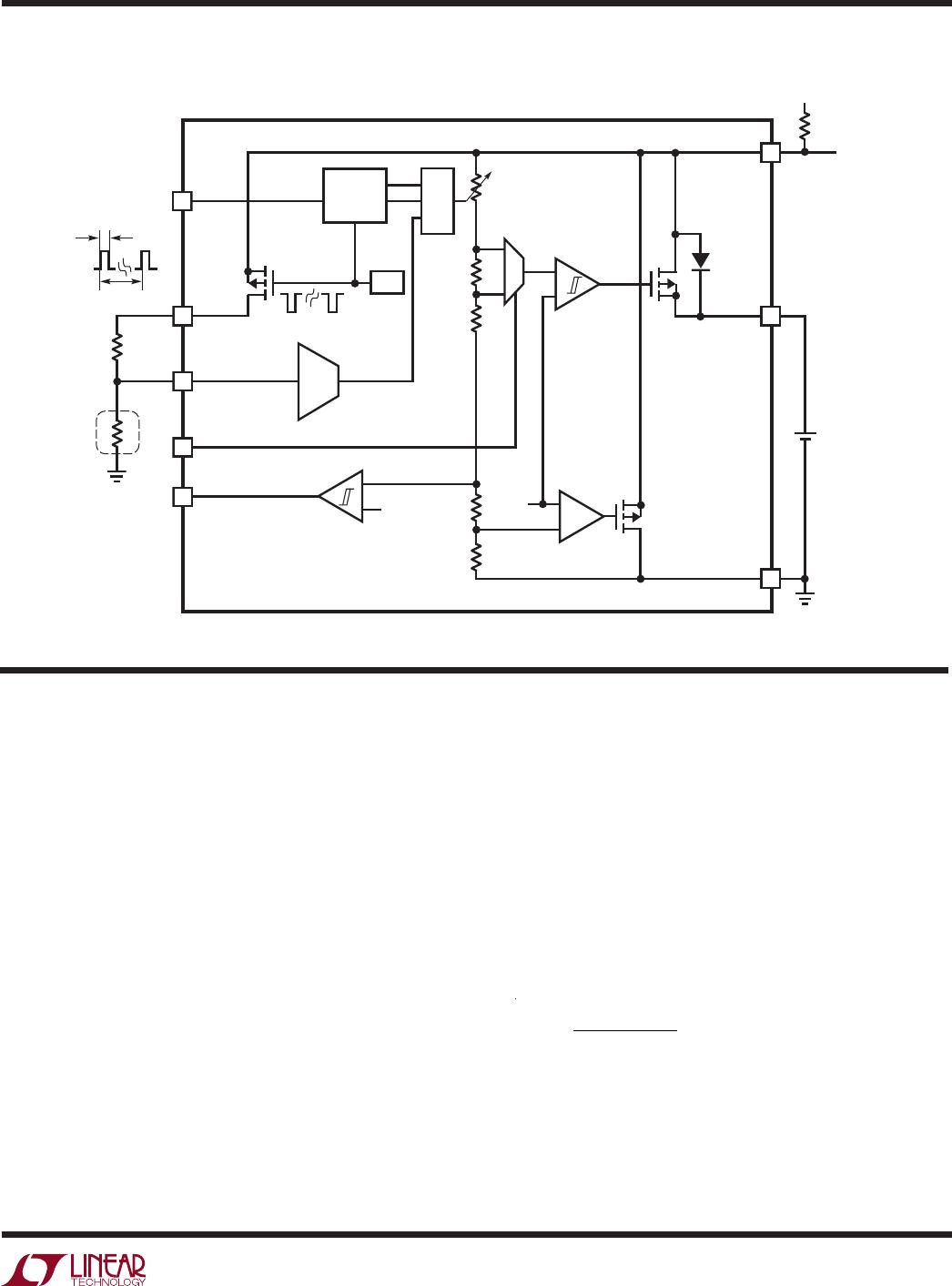
LTC4071
7
4071fc
operaTion
block DiagraM
The LTC4071 provides a simple, reliable, and high per-
formance battery protection and charging solution by
preventing the battery voltage from exceeding a pro-
grammed level. Its shunt architecture requires just one
resistor from the input supply to charge and protect the
battery in a wide range of battery applications. When the
input supply is removed and the battery voltage is below
the high battery output threshold, the LTC4071 consumes
just 550nA from the battery. If the battery voltage falls
below the programmable low battery disconnect level,
the battery disconnects from V
CC
, protecting the battery
from over-discharge either by the load connected to V
CC
or from the LTC4071 quiescent current.
When an input supply is present the battery charges
through the body diode of the internal disconnect PFET,
MP1, until the battery voltage rises above the low-
battery connect threshold. Select an input voltage large
4071 BD
3-STATE
DETECT
OSC
CLK
ADJ
0.9sec – 7sec
PULSED
DUTY CYCLE = 0.003%
30µs – 200µs
NTCBIAS
NTC
R
NOM
10k
10k
T
+
+
+
HBO
LBSEL
LBSEL MUST BE TIED TO V
CC
OR GND
V
CC
BAT
GND
EA
ADC
LTC4071
1.2V
1.2V
MP2
MP1
BODY
DIODE
Li-Ion
BATTERY
+
V
IN
R
IN
SYSTEM
LOAD
enough for V
CC
to reach V
LBC_VCC
to ensure that MP1 turns
on. The user may detect the connected state by observing
periodic pulses at the NTCBIAS pin that only occur once
V
CC
has risen above V
LBC_VCC
, and cease once V
CC
falls
below V
LBD
. Depending on the capacity of the battery and
the input decoupling capacitor, the V
CC
voltage generally
falls to V
BAT
when MP1 turns on; rather than V
BAT
rising
to V
CC
. The internal PFET then reconnects the battery to
V
CC
and the charge rate is determined by the input voltage,
the battery voltage, and the input resistor:
I
CHG
=
V
IN
V
BAT
( )
R
IN
As the battery voltage approaches the float voltage, the
LTC4071 shunts current away from the battery thereby
reducing the charge current. The LTC4071 can shunt up to
50mA. The shunt current limits the maximum charge current.
LTC4071
8
4071fc
operaTion
In cases where the input supply may be shorted to GND
when not supplying power, for example with a solar cell, add
a diode in series with R
IN
to prevent the input from loading
the battery. For more information, refer to the photovoltaic
charger example in the Applications Information section.
Adjustable Float Voltage, V
FLOAT
A built-in 3-state decoder connected to the ADJ pin pro-
vides three programmable float voltages: 4.0V, 4.1V, or
4.2V. The float voltage is programmed to 4.0V when ADJ
is tied to GND, 4.1V when ADJ is floating (disconnected),
and 4.2V when ADJ is tied to V
CC
. The state of the ADJ
pin (and NTC pins) is sampled for about 36µs about once
every 1.2 seconds when HBO is high, and when HBO is
low the sampling rate reduces to about once every 3.6
seconds with the same duty cycle. If V
CC
falls below
V
LBD
, the sampling stops. When it is being sampled, the
LTC4071 applies a relatively low impedance voltage at the
ADJ pin. This technique prevents low level board leakage
from corrupting the programmed float voltage.
NTC Qualified Float Voltage, ∆V
FLOAT(NTC)
The NTC pin voltage is compared against an internal
resistor divider tied to the NTCBIAS pin. This divider has
tap points that are matched to the NTC thermistor resis-
tance/temperature conversion table for a Vishay curve 2
thermistor at temperatures of 40°C, 50°C, 60°C, and 70°C.
The curve 2 thermistor is also designated by a B25/85
value of 3490.
Battery temperature conditioning adjusts the float voltage
down to V
FLOAT_EFF
when the NTC thermistor indicates
that the battery temperature is too high. For a 10k curve 2
thermistor and a 10k NTCBIAS resistor, each 10°C increase
in temperature above 40°C causes the float voltage to drop
by a fixed amount, ∆V
FLOAT(NTC)
, depending on ADJ. If ADJ
is at GND, the float voltage steps down by 50mV for each
10°C temperature increment. If ADJ is floating, the step
size is 75mV. And if ADJ is at V
CC
, the step size is 100mV.
Refer to Table 1 for the range of V
FLOAT_EFF
programming.
Table 1. NTC Qualified Float Voltage
ADJ ∆V
FLOAT(NTC)
TEMPERATURE
V
NTC
AS % OF
NTCBIAS V
FLOAT_EFF
GND 50mV T < 40°C
40°C ≤ T < 50°C
50°C ≤ T < 60°C
60°C ≤ T < 70°C
70°C < T
V
NTC
> 36.5
29.0 < V
NTC
≤ 36.5
22.8 < V
NTC
≤ 29.0
17.8 < V
NTC
≤ 22.8
V
NTC
≤ 17.8
4.000
3.950
3.900
3.850
3.800
Floating 75mV T < 40°C
40°C ≤ T < 50°C
50°C ≤ T < 60°C
60°C ≤ T < 70°C
70°C < T
V
NTC
> 36.5
29.0 < V
NTC
≤ 36.5
22.8 < V
NTC
≤ 29.0
17.8 < V
NTC
≤ 22.8
V
NTC
≤ 17.8
4.100
4.025
3.950
3.875
3.800
V
CC
100mV T < 40°C
40°C ≤ T < 50°C
50°C ≤ T < 60°C
60°C ≤ T < 70°C
70°C < T
V
NTC
> 36.5
29.0 < V
NTC
≤ 36.5
22.8 < V
NTC
≤ 29.0
17.8 < V
NTC
≤ 22.8
V
NTC
≤ 17.8
4.200
4.100
4.000
3.900
3.800
For all ADJ pin settings the lowest float voltage setting is:
3.8V = V
FLOAT_MIN
= V
FLOAT
– 4 • ∆V
FLOAT(NTC)
.
This occurs at NTC thermistor temperatures above 70°C,
or if the NTC pin is grounded.
To conserve power in the NTCBIAS and NTC resistors, the
NTCBIAS pin is sampled at a low duty cycle at the same
time that the ADJ pin state is sampled.
High Battery Status Output: HBO
The HBO pin pulls high when V
CC
rises to within V
HBTH
of the programmed float voltage, V
FLOAT_EFF
, including
NTC qualified float voltage adjustments assuming V
CC
has risen above V
LBC_VCC
.
If V
CC
drops below the float voltage by more than V
HBTH
+
V
HBHY
the HBO pin pulls low to indicate that the battery is
not at full charge. The input supply current to the LTC4071
drops to less than 550nA (typ) as the LTC4071 no longer
shunts current to protect the battery. And the NTCBIAS
sample clock slows to conserve power.
For example, if the NTC thermistor requires the float voltage
to be dropped by 100mV (ADJ = V
CC
and 0.29V
NTCBIAS
< V
NTC
< 0.36V
NTCBIAS
) then the HBO rising threshold
is detected when V
CC
rises past:
V
FLOAT
∆V
FLOAT(NTC)
– V
HBTH
= 4.2V – 100mV – 40mV = 3.96V.
LTC4071
9
4071fc
operaTion
Low Battery Disconnect/Connect: LBD/LBC
The low battery disconnect (V
LBD
) and connect (V
LBC
) volt-
age levels are programmed by the LBSEL pin. As shown
in the Block Diagram the battery disconnects from V
CC
by
shutting off MP1 when the BAT voltage falls below V
LBD
.
This disconnect function protects Li-Ion batteries from
permanent damage due to deep discharge. If the voltage
of a Li-Ion cell drops below a certain level, the cell may be
permanently damaged. Disconnecting the battery from V
CC
prevents the load at V
CC
as well as the LTC4071 quiescent
current from further discharging the battery.
Once disconnected the V
CC
voltage collapses towards
ground. When an input supply is reconnected the bat-
tery charges through the internal body diode of MP1.
The input supply voltage should be larger than V
LBC_VCC
to ensure that MP1 is turned on. When the V
CC
voltage
reaches V
LBC_VCC
, MP1 turns on and connects V
CC
and
BAT. While disconnected, the BAT pin voltage is indirectly
sensed through MP1’s body diode. Therefore V
LBC
varies
with charge current and junction temperature. Please see
the Typical Performance Characteristics section for more
information.
Low Battery Select: LBSEL
The low battery discharge cutoff voltage level is pro-
grammed by the LBSEL pin.
The LBSEL pin allows the user to trade-off battery run-
time and maximum shelf life. A lower battery disconnect
threshold maximizes run time by allowing the battery to
fully discharge before the disconnect event. Conversely,
by increasing the low battery disconnect threshold more
capacity remains following the disconnect event which
extends the shelf life of the battery. For maximum run
time, tie LBSEL to V
CC
so that the battery disconnects at
V
CC
= 2.7V. For extended shelf life, tie LBSEL to GND so
that the battery disconnects at V
CC
= 3.2V. If a high peak
current event is expected, users may temporarily select
the lower disconnect threshold. This avoids disconnect-
ing the battery too early when the load works against the
battery series resistance and temporarily reduces V
CC
.

LTC4071EMS8E#PBF

Mfr. #:
Manufacturer:
Analog Devices / Linear Technology
Description:
Battery Management Li-Ion/Polymer Shunt Battery Charger System with Low Battery Disconnect
Lifecycle:
New from this manufacturer.
Delivery:
DHL FedEx Ups TNT EMS
Payment:
T/T Paypal Visa MoneyGram Western Union