LTC4071
11
4071fc
applicaTions inForMaTion
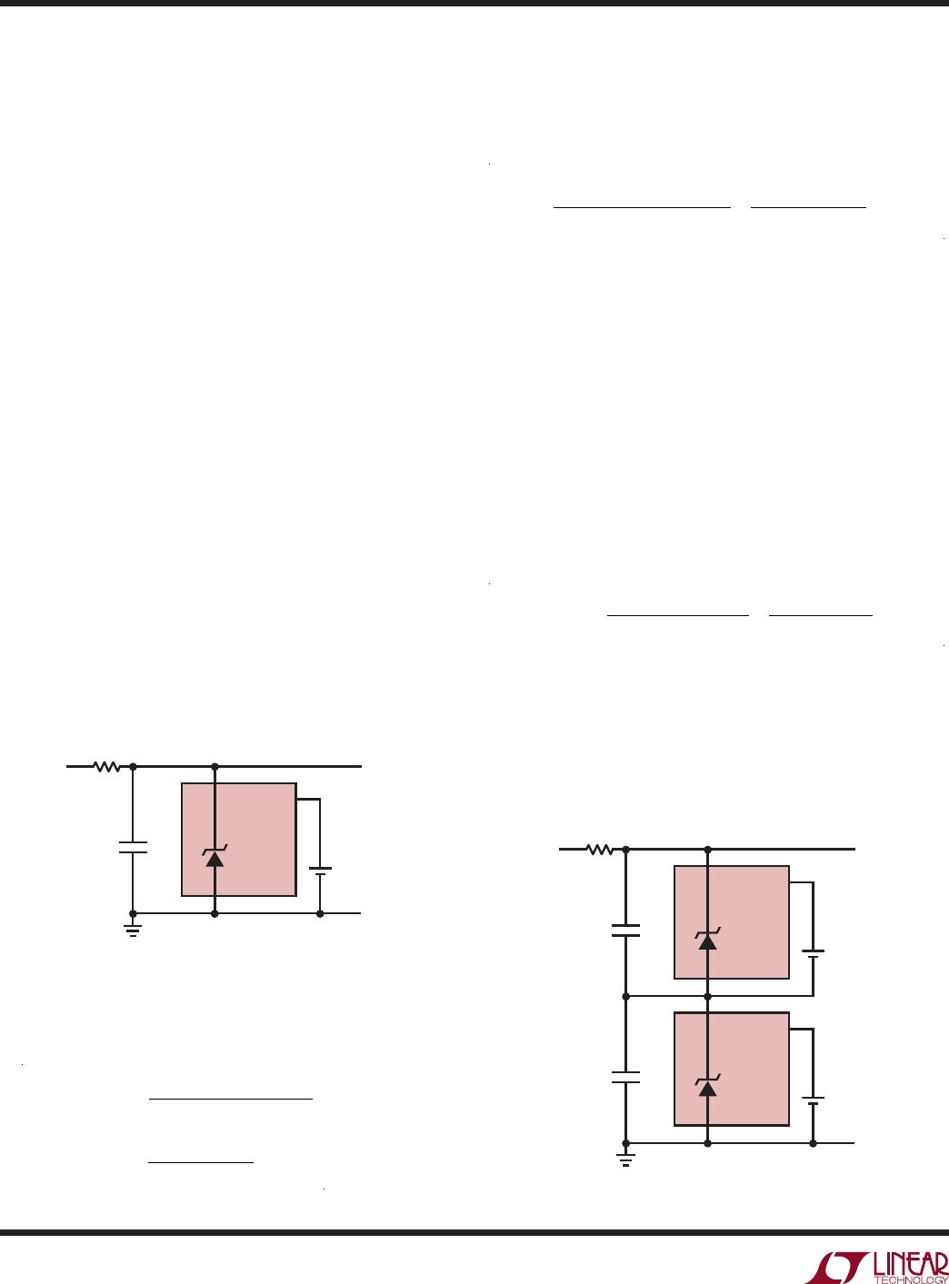
The GND pin of the top device is simply connected to
the V
CC
pin of the bottom device. Care must be taken in
observing the HBO status output pin of the top device as
this signal is no longer ground referenced. Likewise for
the control inputs of the top device; tie ADJ and LBSEL
of the top device to the local GND or V
CC
pins. Also, the
wall adapter must have a high enough voltage rating to
charge both cells.
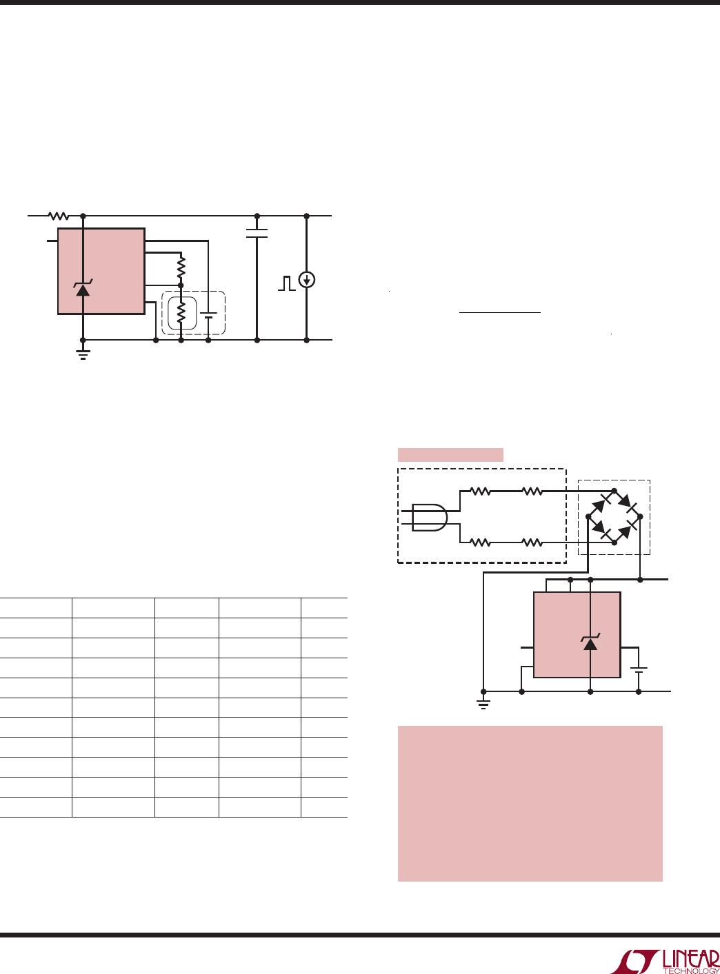
NTC Protection
The LTC4071 measures battery temperature with a negative
temperature coefficient thermistor thermally coupled to the
battery. NTC thermistors have temperature characteristics
which are specified in resistance-temperature conversion
tables. Internal NTC circuitry protects the battery from
excessive heat by reducing the float voltage for each
10°C rise in temperature above 40°C (assuming a Vishay
thermistor with a B
25/85
value of 3490).
The LTC4071 uses a ratio of resistor values to measure
battery temperature. The LTC4071 contains an internal
fixed resistor voltage divider from NTCBIAS to GND with
four tap points; NTC
TH1
–NTC
TH4
. The voltages at these
tap points are periodically compared against the voltage at
the NTC pin to measure battery temperature. To conserve
power, the battery temperature is measured periodically
by biasing the NTCBIAS pin to V
CC
about once every 1.5
seconds.
The voltage at the NTC pin depends on the ratio of NTC
thermistor value, R
NTC
, and a bias resistor, R
NOM
. Choose
R
NOM
equal to the value of the thermistor at 25°C. R
NOM
is 10k for a Vishay NTHS0402N02N1002F thermistor with
a B
25/85
value of 3490. R
NOM
must be connected from
NTCBIAS to NTC. The ratio of the NTC pin voltage to the
NTCBIAS voltage when it is pulsed to V
CC
is:
R
NTC
R
NTC
+ R
NOM
( )
When the thermistor temperature rises, the resistance
drops; and the resistor divider between R
NOM
and the
thermistor lowers the voltage at the NTC pin.
An NTC thermistor with a different B
25/85
value may also
be used with the LTC4071. However the temperature trip
points are shifted due to the higher negative temperature
coefficient of the thermistor. To correct for this difference
add a resistor, R
FIX
, in series with the thermistor to shift
the ratio:
FIX
NTC
R
FIX
+ R
NTC
+ R
NOM
( )
Up to the internal resistive divider tap points: NTC
TH1
through NTC
TH4
. For a 100k thermistor with a B
25/85
value of 3950, e.g. NTHS0402N01N1003F, at 70°C (with
R
NOM
= 100k) choose R
FIX
= 3.92k. The temperature trip
points are found by looking up the curve 1 thermistor R/T
values plus R
FIX
that correspond to the ratios for NTC
TH1
= 36.5%, NTC
TH2
= 29%, NTC
TH3
= 22.8%, and NTC
TH4
= 17.8%. Selecting R
FIX
= 3.92k results in trip points of
39.9°C, 49.4°C, 59.2°C and 69.6°C.
Another technique may be used without adding an ad-
ditional component. Instead decrease R
NOM
to adjust the
NTC
TH
thresholds for a given R/T thermistor profile. For
example, if R
NOM
= 88.7k (with the same 100k thermis-
tor) then the temperature trip points are 41.0°C, 49.8°C,
58.5°C and 67.3°C.
When using the NTC features of the LTC4071 it is important
to keep in mind that the maximum shunt current increases
as the float voltage, V
FLOAT_EFF
drops with NTC conditioning.
Reviewing the single-cell battery charger application with
a 12V wall adapter in Figure 2; the input resistor should be
increased to 165Ω such that the maximum shunt current
does not exceed 50mA at the lowest possible float voltage
due to NTC conditioning, V
FLOAT_MIN
= 3.8V.
Thermal Considerations
At maximum shunt current, the LTC4071 may dissipate up
to 205mW. The thermal dissipation of the package should
be taken into account when operating at maximum shunt
current so as not to exceed the absolute maximum junc-
tion temperature of the device. With θ
JA
of 40°C/W, in the
MSOP package, at maximum shunt current of 50mA the
junction temperature rise is about 8°C above ambient.
With θ
JA
of 76°C/W in the DFN package, at maximum
shunt current of 50mA the junction temperature rise is
about 16°C above ambient. The junction temperature, T
J
,
is calculated depending on ambient temperature, T
A
, power