LTC4071
13
4071fc
Figure 6. Simple Photovoltaic Charger
Figure 7. Piezoelectric Energy Harvester with Battery Backup
LTC4071
BAT
GND
Li-Ion
BATTERY
V
CC
+
4071 F07
LTC4071
LTC3588-1
BAT
LBSEL
LBSEL
GND GND
PFCB-W14
Li-Ion
BATTERY
V
CC
+
1µF
PZ1
PZ2
D1
D0
SW
V
OUT
V
IN2
4.7µF
3.3V
SYSTEM
LOAD
100µF
10µH
CAPV
IN
V
IN2
22µF
1µF
MMSD4148T1
15k
applicaTions inForMaTion
the four input 249k resistors are sized for acceptable UL
leakage in the event that one of the resistors short. Here,
the LTC4071 will fully charge the battery from the AC line
while meeting the UL specification with 104µA of available
charge current.
A simple photovoltaic (PV) application for the LTC4071
is illustrated in Figure 6. At low V
CC
voltage, PV current
flows to both the system at V
CC
as well as the battery.
When V
CC
reaches the programmed float voltage (4.1V
with ADJ floating) then the LTC4071 shunts excess current
not used by the load, limiting V
CC
to 4.1V and effectively
reducing the battery charge current to zero. If the PV cells
stop supplying current, the battery supports the load at
V
CC
through the LTC4071. Add a diode in series with the
PV cells to prevent reverse leakage of the PV cells from
draining the battery. If the battery discharges to the point
where V
CC
falls below V
LBD
(3.2V with LBSEL tied to
GND) the LTC4071 disconnects the load from the battery
to protect the battery from over discharge.
Typically, solar cells are inherently limited in current, but
this circuit may require a resistor, R
IN
, in series with the
LTC4071 for high current solar cells. Select R
IN
such that
the LTC4071 never needs to shunt more than 50mA.
The simple schematic in Figure 7 illustrates a complete
piezoelectric energy harvesting application using the
LTC4071 to charge and protect Li-Ion cells along with the
LTC3588-1 to rectify and regulate energy generated from
a piezoelectric generator to a fixed 3.3V load.
LTC4071
BAT
NTCBIAS
NTC
LBSEL
ADJ
1µF
GND
DS16003
Li-Ion
V
CC
+
4071 F06
FLOAT
* NTHS0402N02N1002F
** JAMECO 171061
10k
T*
SYSTEM LOAD
**
**
**
**
+
+
+
+
LTC4071
14
4071fc
This system has two modes of operation, charging where
the batteries are being charged from energy harvested from
the piezoelectric generator while the load is negligible.
And discharging, where the load is pulling current from
the batteries, but insufficient energy is being harvested
to power the load.
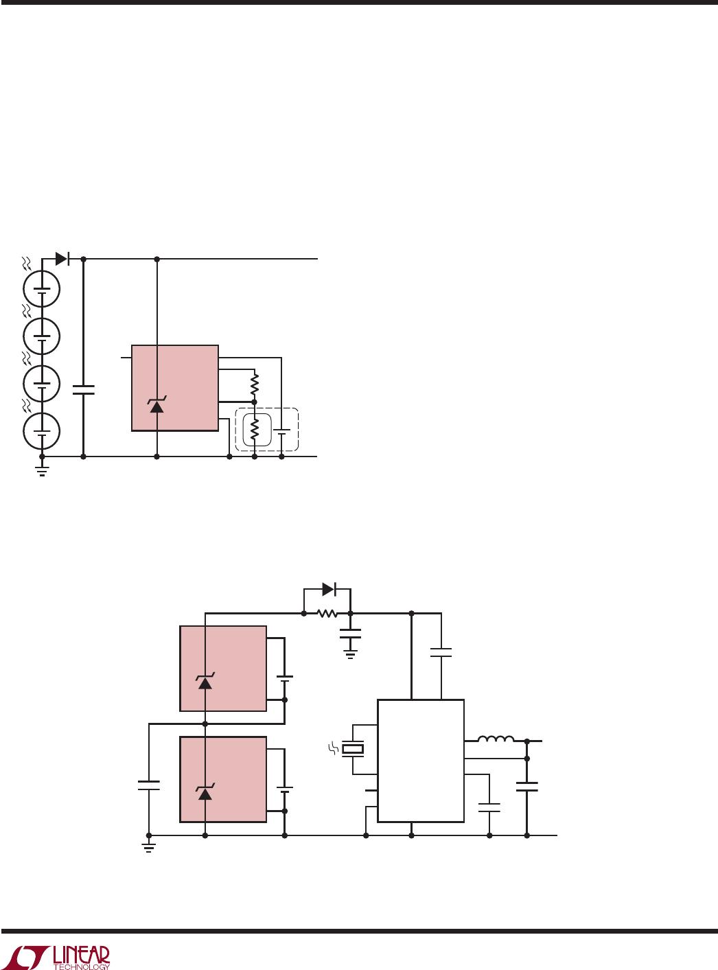
This application allows the load to periodically draw more
current than would otherwise be available from the piezo-
electric generator by storing excess charge in a stack of
two Li-Ion cells. Each Li-Ion cell is protected from over-
charge and over discharge by a LTC4071 shunt regulator.
The two LTC4071s regulate V
IN
of the LTC3588-1 to 8.2V
(with both ADJ pins floating) shunting any excess current
that is not used by the load once the batteries achieve
their float voltages. When the load requires more current
than is available from the piezoelectric generator, the
voltage at V
IN
droops and current is supplied from the two
Li-Ion cells to power the step-down switching regulator.
If the load pulls enough current to discharge the batteries
below V
LBD
, the LTC4071s disconnect the batteries, and
V
IN
collapses until the piezoelectric generator resumes
supplying current.
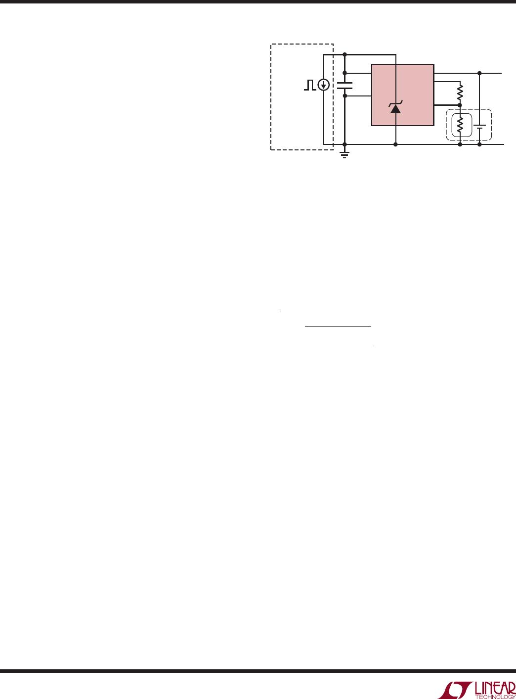
The application in Figure 8 illustrates how to implement
“ship-mode,” where a battery is co-packaged with the
LTC4071 and then the entire device is latched-off, leaving
the battery fully charged but with the LTC4071 switched off.
The co-packaged battery and LTC4071 can then be stored
with a long shelf-life before being activated for normal use.
Ship-mode is triggered by pulling enough current through
the LTC4071 so as to drop V
CC
below the LBD threshold.
The current pulse amplitude should be less than 400mA
with a duration of less than 10ms. The peak current neces-
sary, I
PK
, depends on the equivalent series resistance of
the battery, B
ESR
, summed with the R
DSON
of the BAT-V
CC
FET, the battery voltage, V
BAT
and the selected disconnect
voltage, V
LBD
:
I
PK
=
V
BAT
V
LBD
R
DSON
+ BESR
Users may test that ship mode has been triggered by
simply checking if V
CC
is at GND and that there are no
longer any NTCBIAS pulses.
Re-activation of the LTC4071 and the battery requires
either applying power normally, or briefly shorting V
CC
to BAT to turn it on.
applicaTions inForMaTion
Figure 8. LTC4071 Ship-Mode Application for Extended Shelf Life
LTC4071
BAT
NTCBIAS
NTC
ADJ
LBSEL
1µF
CURRENT PULSE
TO TRIGGER
SHIP-MODE
GND
Li-Ion
V
CC
I
PK
0
+
4071 F08
*NTHS0402N02N1002F
10k
T*
LTC4071
15
4071fc
package DescripTion
DDB Package
8-Lead Plastic DFN (3mm × 2mm)
(Reference LTC DWG # 05-08-1702 Rev B)
2.00 ±0.10
(2 SIDES)
NOTE:
1. DRAWING CONFORMS TO VERSION (WECD-1) IN JEDEC PACKAGE OUTLINE M0-229
2. DRAWING NOT TO SCALE
3. ALL DIMENSIONS ARE IN MILLIMETERS
4. DIMENSIONS OF EXPOSED PAD ON BOTTOM OF PACKAGE DO NOT INCLUDE
MOLD FLASH. MOLD FLASH, IF PRESENT, SHALL NOT EXCEED 0.15mm ON ANY SIDE
5. EXPOSED PAD SHALL BE SOLDER PLATED
6. SHADED AREA IS ONLY A REFERENCE FOR PIN 1 LOCATION ON THE TOP AND BOTTOM OF PACKAGE
0.40 ± 0.10
BOTTOM VIEW—EXPOSED PAD
0.56 ± 0.05
(2 SIDES)
0.75 ±0.05
R = 0.115
TYP
R = 0.05
TYP
2.15 ±0.05
(2 SIDES)
3.00 ±0.10
(2 SIDES)
14
85
PIN 1 BAR
TOP MARK
(SEE NOTE 6)
0.200 REF
0 – 0.05
(DDB8) DFN 0905 REV B
0.25 ± 0.05
2.20 ±0.05
(2 SIDES)
RECOMMENDED SOLDER PAD PITCH AND DIMENSIONS
0.61
±
0.05
(2 SIDES)
1.15 ±0.05
0.70 ±0.05
2.55 ±0.05
PACKAGE
OUTLINE
0.25 ± 0.05
0.50 BSC
PIN 1
R = 0.20 OR
0.25 × 45°
CHAMFER
0.50 BSC
Please refer to http://www.linear.com/designtools/packaging/ for the most recent package drawings.

LTC4071EMS8E#PBF

Mfr. #:
Manufacturer:
Analog Devices / Linear Technology
Description:
Battery Management Li-Ion/Polymer Shunt Battery Charger System with Low Battery Disconnect
Lifecycle:
New from this manufacturer.
Delivery:
DHL FedEx Ups TNT EMS
Payment:
T/T Paypal Visa MoneyGram Western Union