LVPECL
Receiver
50
Ohms
50
Ohms
VDD
VDD_Rx
Z
o
= 50 Ohms
Z
o
= 50 Ohms
ZL40205
clk_p
clk_n
R
For VDD = 2.5 V: R = 20 Ohms
For VDD = 3.3 V: R = 50 Ohms
Figure 14 - LVPECL Parallel Output Termination
ZL40205 Data Sheet
12
Microsemi Corporation
R2 R2
VDD
VDD_Rx
Z
o
= 50 Ohms
Z
o
= 50 Ohms
ZL40205
clk_p
clk_n
For VDD = 2.5 V: R1 = 250 Ohms, R2 = 62.5 Ohms
For VDD = 3.3 V: R1 = 127 Ohms, R2 = 82 Ohms
VDD_Rx
R1 R1
LVPECL
Receiver
Figure 15 - LVPECL Parallel Thevenin-Equivalent Output Termination
R2 R2
VDD
VDD_Rx
Z
o
= 50 Ohms
Z
o
= 50 Ohms
ZL40205
clk_p
clk_n
For VDD_Rx = 2.5 V: R1 = 250 Ohms,
R2 = 62.5 Ohms
For VDD_Rx = 3.3 V: R1 = 127 Ohms,
R2 = 82 Ohms
VDD_Rx
R1 R1
LVPECL
Receiver
RR
For VDD = 2.5 V: R = 60 Ohms
For VDD = 3.3 V: R = 120 Ohms
100 nF
100 nF
Figure 16 - LVPECL AC Output Termination
ZL40205 Data Sheet
13
Microsemi Corporation
VDD VDD_Rx
Z
o
= 50 Ohms
Z
o
= 50 Ohms
ZL40205
clk_p
clk_n
100 nF
100 nF
50
CML
Receiver
50
R
For VDD = 2.5 V: R = 60 Ohms
For VDD = 3.3 V: R = 120 Ohms
R
Figure 17 - LVPECL AC Output Termination for CML Inputs
ZL40205 Data Sheet
14
Microsemi Corporation
3.3 Device Additive Jitter
The ZL40205 clock fanout buffer is not intended to filter clock jitter. The jitter performance of this type of device is
characterized by its additive jitter. Additive jitter is the jitter the device would add to a hypothetical jitter-free clock as
it passes through the device. The additive jitter of the ZL40205 is random and as such it is not correlated to the jitter
of the input clock signal.
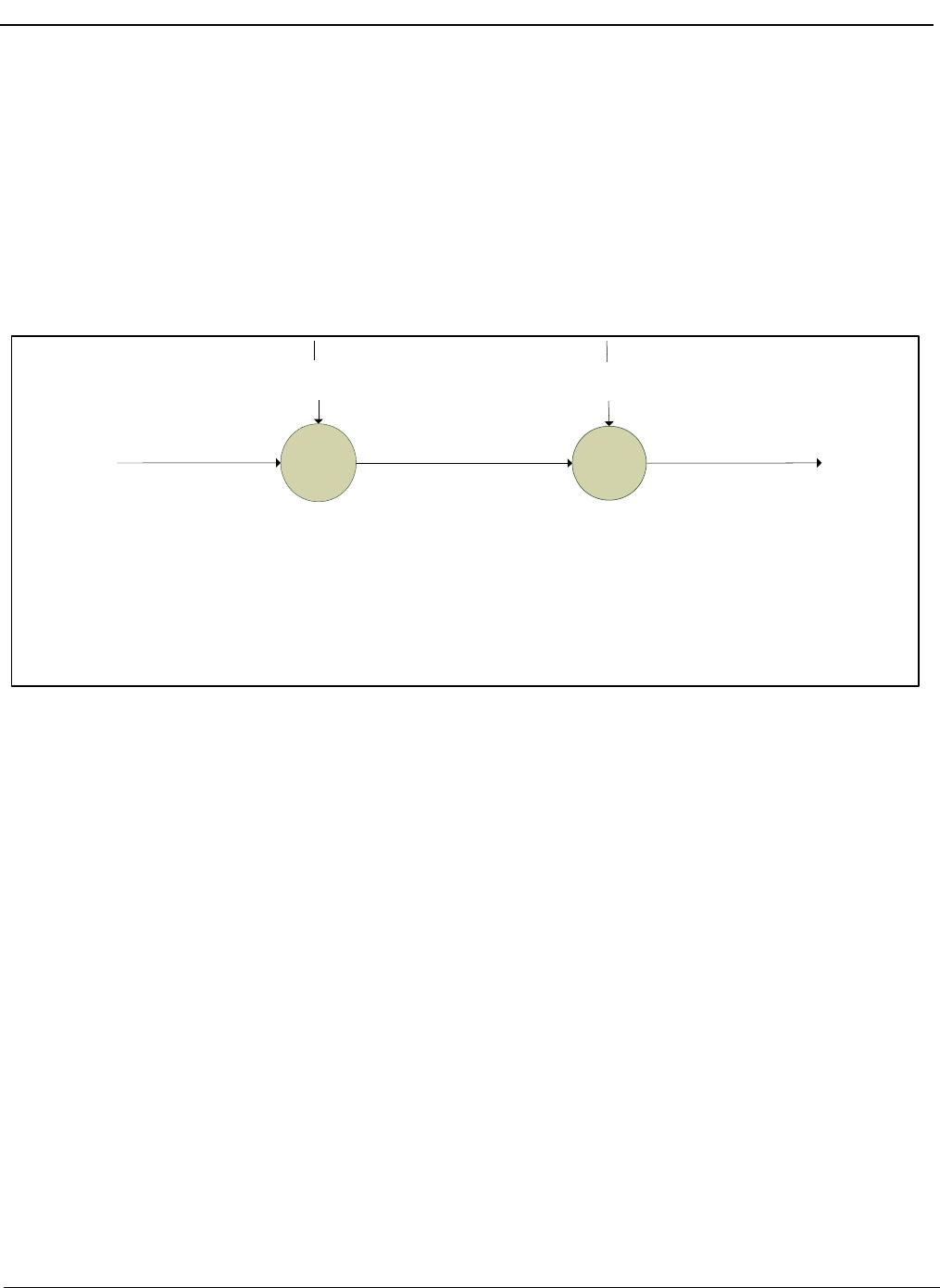
The square of the resultant random RMS jitter at the output
of the ZL40205 is equal to the sum of the squares of the
various random RMS jitter sources including: input clock jitter; additive jitter of the buffer; and additive random jitter
due to power supply noise. There may be additional deterministic jitter sources, but they are not shown in Figure
18.
+
J
in
2
J
out
2
= J
in
2
+J
add
2
+J
ps
2
J
add
2
J
ps
2
J
in
= Random input clock jitter (RMS)
J
add
= Additive jitter due to the device (RMS)
J
ps
= Additive jitter due to power supply noise (RMS)
J
out
= Resultant random output clock jitter (RMS)
+
Figure 18 - Additive Jitter

ZL40205LDG1

Mfr. #:
Manufacturer:
Microchip / Microsemi
Description:
Clock Buffer 1:6 LVPECL Fanout Buffer w/Int. Term.
Lifecycle:
New from this manufacturer.
Delivery:
DHL FedEx Ups TNT EMS
Payment:
T/T Paypal Visa MoneyGram Western Union

Products related to this Datasheet