MAX6974/MAX6975
(PWM) value. Each output current driver in the R, G,
and B ports has a unique 12-bit (MAX6974) or 14-bit
(MAX6975) PWM control value providing fine resolution
adjustment of average current output. Each bit time of
the PWM corresponds to one period of CLKI (T
CLKI
).
The PWM setting determines the amount of time, out of
the total period, that the output is on. The subframes
have PWM off-zones at the start (t
SPWM
) and end
(t
EPWM
) of the PWM period (see Figure 3). The sub-
frame period and PWM off zones are shown in Table 2
for each device.
The MAX6974 subdivides each subframe by 4096
(12-bit) PWM steps and has 16 cycle off zones, leaving
an active PWM region of 4064 PWM steps ranging from
16 to 4079. The MAX6975 subdivides each subframe
by 16,384 (14-bit) PWM steps and has 32 cycle off
zones, leaving an active PWM region of 16,320 PWM
steps ranging from 32 to 16,351. The PWM phase for
outputs R0, R2, R4, R6, G0, G2, G4, G6, B0, B2, B4,
and B6 use phasing with the outputs on first and off
second. Inverse phasing is used for outputs R1, R3,
R5, R7, G1, G3, G5, G7, B1, B3, B5, and B7 as shown
in Figure 3 to balance the timing of loads on the LED
anode power supply.
In multiplexed operation, the subframes are shared
between MUX0 and MUX1 active times, effectively
reducing the number of subframes by 2.
LED-Intensity Control Example
The three levels of intensity control are shown in Figure 2
for one LED output driver in a MAX6974 in nonmulti-
plexed mode. As an example, the CALDAC is set to
169
DEC,
setting the port output current level to 21.8mA.
The global-intensity PDM value is set to 96
DEC
, producing
an even distribution of ON subframes out of the 128
24-Output PWM LED Drivers
for Message Boards
10 ______________________________________________________________________________________
R0, R2, R4, R6
G0, G2, G4, G6
B0, B2, B4, B6
R1, R3, R5, R7
G1, G3, G5, G7
B1, B3, B5, B7
R0, R2, R4, R6
G0, G2, G4, G6
B0, B2, B4, B6
R1, R3, R5, R7
G1, G3, G5, G7
B1, B3, B5, B7
SUBFRAME (n) SUBFRAME (n + 1)
t
SPWM
t
EMUX
t
EMUX
MUX0
SUBFRAME (n), MUX0 SUBFRAME (n), MUX1
MUX1
t
SPWM
t
SPWM
t
EPWM
MULTIPLEXED
NONMULTIPLEXED
t
SPWM
t
EPWM
ON/OFF PHASING
OFF/ON PHASING
ON/OFF PHASING
OFF/ON PHASING
50% 75%
100%25%
75%75%
75% 75%
Figure 3. Multiplexed and Nonmultiplexed Output Driver Phasing and Example PWM Values
PART
SUBFRAME
(T
CLKI
)
t
SPWM
(T
CLKI
)
t
EPWM
(T
CLKI
)
t
EMUX
(T
CLKI
)
MAX6974 4096 16 16 16
MAX6975 16,384 32 32 32
Table 2. Subframe and PWM Timing
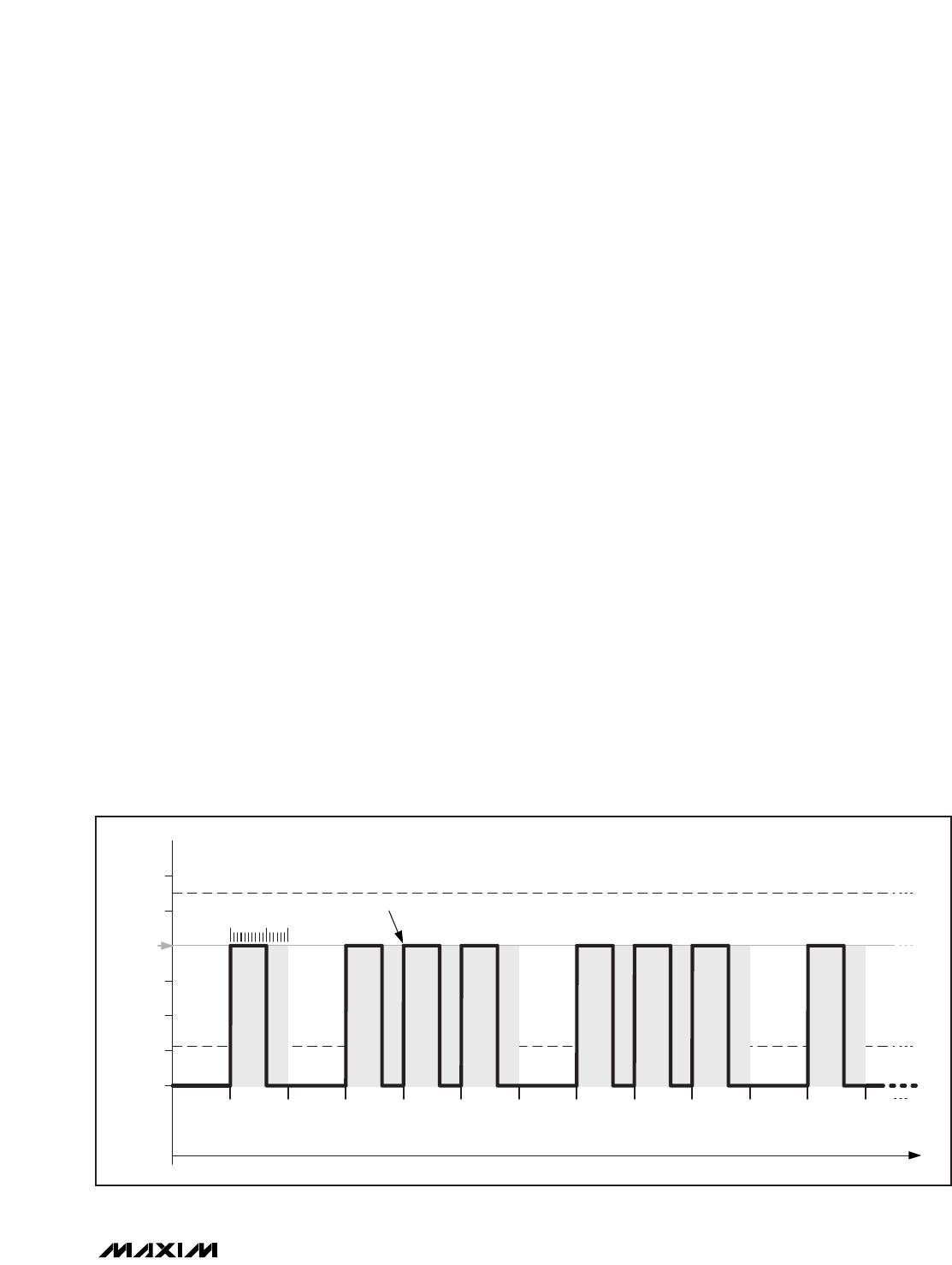
possible (shown in Figure 4 as subframes 1, 3, 4, 5, etc).
Each subframe can be ON for a PWM duration set by the
individual PWM value. The PWM value setting of
2560
DEC
out of 4096 (12-bit) results in a further reduction
of current ON time (shown in bold trace).
The internal PDM logic spreads the on subframes as
evenly as possible among the off subframes to keep
the effective scanning frequency high.
For applications with a slower clock speed, the
MAX6975 can increase the display refresh rate by a
factor of four to eliminate visible flicker. Setting configu-
ration bit D4 (GLB4) to 1 activates the increased
refresh rate (see Table 6). The increased refresh rate
reduces the number of global-intensity settings by a
factor of four (see Table 3).
MAX6974 Video-Frame Timing
The MAX6974 supports up to 60 video frames per
second (fps). The following equation shows the
required clock frequency to support 60 video fps:
60 (video fps) x 4096 (clocks per 12-bit PWM period) x
128 (global-intensity subframes) = 31.5MHz.
The MAX6974 supports up to a 33MHz clock signal
(~63fps).
Each 12-bit PWM period contains 4096 clock cycles;
multiply that number by 128 (number of global-intensity
subframes) to obtain the required number of clock cycles
(524,288) per video frame. The MAX6974 requires 36
bits (12 bits per color multiplied by three colors) to drive
an RGB pixel. The maximum pixel data that the
MAX6974 can send per video frame is 524,288 / 36 or
14,563 pixels, corresponding to 1820 cascaded
MAX6974s.
MAX6975 Video-Frame Timing
The MAX6975 also supports up to 60 video frames per
second (fps). The following equation shows the
required clock frequency to support 60 video fps:
60 (video fps) x 16,384 (clocks per 14-bit PWM period)
x 32 (global-intensity subframes) = 31.5MHz.
The MAX6975 supports up to a 33MHz clock signal
(~63fps).
Each 14-bit PWM period contains 16,384 clock cycles;
multiply 16,384 by 32 (global-intensity subframes) to
obtain the required number of clock cycles (524,288)
per video frame. The MAX6975 requires 42 bits (14 bits
per color multiplied by three colors) to drive an RGB
pixel. The maximum pixel data that the MAX6975 can
send per video frame is 524,288 / 42 or 12,483 pixels,
corresponding to 1560 cascaded MAX6975s.
Multiplexed vs. Nonmultiplexed Operation
The MAX6974/MAX6975 can double the number of
LEDs driven from 24 to 48 through multiplexing. When
multiplexing, the two outputs, MUX0 and MUX1, drive
MAX6974/MAX6975
24-Output PWM LED Drivers
for Message Boards
______________________________________________________________________________________ 11
169d = 20
SUBFRAME NUMBER
5
10
15
25
30mA MAX
6mA MIN
(mA)
01234567891011
CALDAC CURRENT
OUTPUT LED CURRENT
PWM = 2560/4096
ONE FRAME IS 2
19
(524,288) CLKI CYCLES LONG
GLOBAL PDM = 96/128 SUBFRAMES
ON ON ON ON ON ON ON ON
Figure 4. The three levels of LED current control (CALDAC, global-intensity PDM, and individual PWM) modulate the average output
current.
MAX6974/MAX6975
two external pnp transistors, such as FMMTL717, used
as common-anode power switches (see Figure 5).
Setting configuration bit D0 to 1 enables multiplex
operation. MUX0 and MUX1 alternate the LED anode
drive voltage between two sets of LEDs. The R, G, and
B ports provide individual PWM control during alternate
24-Output PWM LED Drivers
for Message Boards
12 ______________________________________________________________________________________
R0
R1
R2
R3
R4
R5
R6
R7
(REDS)
(REDS) (GREENS) (GREENS) (BLUES) (BLUES)
Q1
FMMTL717
R1
560Ω
R2
180Ω
C1
120pF
+5.55V
Q2
FMMTL717
R1
560Ω
R2
180Ω
C1
120pF
G1
G2
G3
G4
G5
G6
G7
G0
B1
B2
B3
B4
B5
B6
B7
B0
MUX0
MUX1
SUBFRAME 15
MUX1
16,384 CLKs
SUBFRAME 0
MUX0
16,384 CLKs
SUBFRAME 0
MUX1
16,384 CLKs
SUBFRAME 1
MUX0
16,384 CLKs
SUBFRAME 1
MUX1
16,384 CLKs
SUBFRAME 14
MUX0
16,384 CLKs
SUBFRAME 14
MUX1
16,384 CLKs
SUBFRAME 15
MUX0
16,384 CLKs
SUBFRAME 15
MUX1
16,384 CLKs
SUBFRAME 0
MUX0
16,384 CLKs
ONE COMPLETE 524,288 CLOCK CYCLE MULTIPLEXED VIDEO FRAME
Figure 5. MAX6975 Multiplexing Two Sets of Eight RGB Pixels with a Single LED Supply and Subframe Timing

MAX6975ATL+

Mfr. #:
Manufacturer:
Maxim Integrated
Description:
LED Lighting Drivers 24-Output PWM LED Driver
Lifecycle:
New from this manufacturer.
Delivery:
DHL FedEx Ups TNT EMS
Payment:
T/T Paypal Visa MoneyGram Western Union

Products related to this Datasheet