MUX cycles as shown in Figure 3. The alternating MUX
cycles reduce the global-intensity resolution (the num-
ber of subframes) by half, which reduces the average
LED current by half.
Watchdog
A selectable watchdog timer monitors serial-interface
inputs CLKI, DIN, and LOADI. Enabling the watchdog
timer requires that CLKI, DIN, and LOADI toggle at
least once every 40ms. If any of these transitions fails to
occur, then the individual-intensity PWM data latches
clear. This condition effectively blanks the LEDs.
Update the individual-intensity PWM data registers to
turn the LEDs back on. The watchdog timeout does not
affect the calibration or global-intensity data, the clock
synchronization, or multiplexed/nonmultiplexed setting.
Use the watchdog functionality in safety-critical appli-
cations where a blanked display is safer than an incor-
rect display.
LED Open-Circuit and
Overtemperature Detection
The MAX6974/MAX6975 feature two fault detection func-
tions: open-circuit LED outputs and overtemperature. An
LED open circuit is detected on driver outputs by moni-
toring for output voltages below 200mV. When an open
circuit is detected, the MAX6974/MAX6975 increments
a fault counter included in the serial-interface protocol
that can be routed back to the host transmitter for diag-
nostics. Any number of open-circuit LEDS, multiplexed
or nonmultiplexed, can be detected, however, only one
counter increment occurs per device.
The MAX6974/MAX6975 detect die temperatures
above T
DIE
= +165°C and disable all output drivers by
setting all PWM data to zero. The fault counter in the
serial-interface protocol is incremented by one count
for each cascaded device with an overtemperature
condition. The output drivers are turned back on when
the die temperature falls below T
DIE
= +150°C. The
fault counter value is distinguished between LED open-
circuit and overtemperature conditions by the serial-
interface command used at the time of detection (see
the
Serial Interface
section for more details).
Commands
The MAX6974/MAX6975 have four commands used to
load all operating mode and LED output current data.
MAX6974/MAX6975
24-Output PWM LED Drivers
for Message Boards
______________________________________________________________________________________ 13
PART
MUX
BIT
OPERATION
PWM
RES.
TOTAL CLOCKS PER
PWM SUBFRAME
USEABLE CLOCKS PER
PWM SUBFRAME
MAXIMUM PWM
DUTY CYCLE
0 Nonmultiplex
MAX6974
1 Multiplex
12 bits 4096 4064 4064 / 4096 = 99.22%
0 Nonmultiplex
MAX6975
1 Multiplex
14 bits 16,384 16,320 16,320 / 16,384 = 99.61%
Table 3. MAX6974/MAX6975 Timing Comparison
PART
GLB4
BIT
MUX
BIT
OPERATION
GLOBAL
PDM
RES.
SUBFRAMES
PER FRAME
CLOCKS
PER
FRAME
CLOCK
FREQUENCY (MHz)
FOR 50fps
CLOCK
FREQUENCY (MHz)
FOR 60fps
X 0 Nonmultiplex 7 bits 128
MAX6974
X 1 Multiplex 6 bits 64
524,288 26.2144 31.45728
0 Nonmultiplex 5 bits 32
0
1 Multiplex 4 bits 16
524,288 26.2144 31.45728
0 Nonmultiplex 3 bits 8
MAX6975
1
1 Multiplex 2 bits 4
131,072 6.5536 7.8643
MAX6974/MAX6975
Each command is uniquely identified by two bits, C1
and C0, embedded in the serial-interface protocol
structure. The commands Load CALDAC, Load Global-
Intensity PDM, and Load Configuration each require 24
bits of data (3 bytes) for every cascaded device. The
number of bits required for the command load individual
PWM varies by device and multiplex mode of operation.
Each cascaded device can receive unique data for
CALDACs, global intensity, configuration, and individual
PWM output drivers. Generally, all cascaded devices
are operated in the same configuration mode. The data
bytes are transmitted MSB first for all commands. The
commands are communicated to all cascaded devices
by the host using the synchronous serial-interface and
protocol structure (see the
Serial Interface
section for
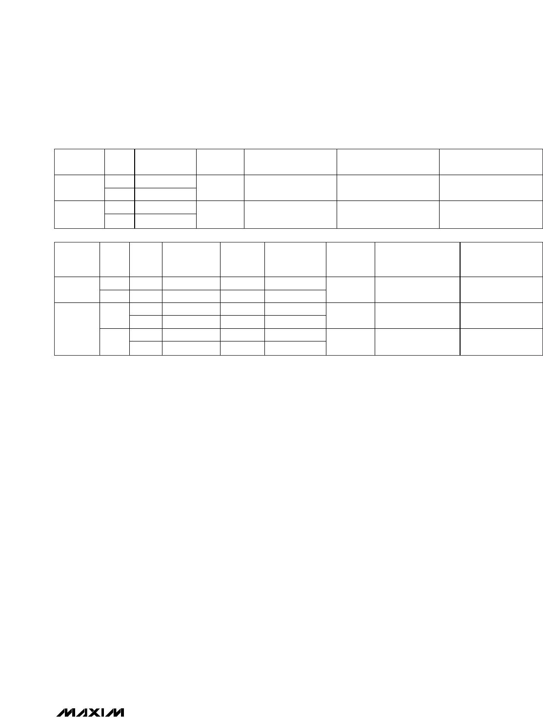
details). The four commands and the data lengths for
each command are shown in Table 4.
The MAX6974, operating in nonmultiplexed mode,
requires twenty-four 12-bit individual PWM data (288
bits total) and requires forty-eight 12-bit data (576 bits
total) in multiplexed operation mode. Similarly, the
MAX6975, operating in nonmultiplexed mode, requires
twenty-four 14-bit individual-intensity PWM data (336
bits total) and requires forty-eight 14-bit (672 bits total)
data in multiplexed mode. The individual PWM data are
loaded into an intermediate latch and transferred to the
actual PWM latches at subframe 0 and PWM clock 0.
The R, G, and B calibration DACs are loaded with 8-bit
data each in nonmultiplexed and multiplexed modes.
Data is updated immediately into the CALDAC latches
(see Table 8)
.
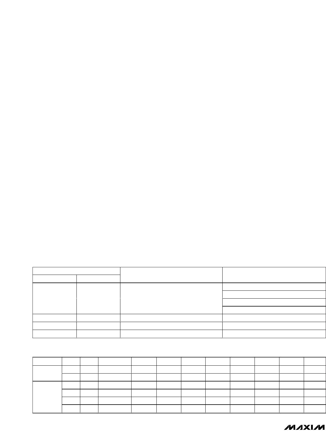
The MAX6974/MAX6975 require one data byte to set the
global-intensity PDM for all output drivers. The global-
intensity PDM data has a variable number of active bits
depending on the multiplex operating mode and, for
the MAX6975, the global-quarter setting. The number of
bits used for global-intensity control is always justified
to the LSB of the data byte, as shown in Table 5. One
byte of data is sent three times with the global-intensity
PDM data bits justified to the LSB. Data is updated into
the PWM latches at subframe 0 and PWM clock 0 (see
Table 9)
.
When using the MAX6975 5-bit global-intensity setting,
the settings range from 0 to 63 to set the global intensity
from 1 to 64 subframes ON to 64 out of 64 subframes ON.
When using the MAX6974 7-bit global-intensity setting,
the settings range from 0 to 127 to set the global inten-
sity from 1 out of 128 subframes ON to 128 out of 128
subframes ON.
24-Output PWM LED Drivers
for Message Boards
14 ______________________________________________________________________________________
CMD[1:0]
C1 C0
COMMAND DATA LENGTH PER CASCADED DEVICE
288 bits (MAX6974 nonmultiplexed)
576 bits (MAX6974 multiplexed)
336 bits (MAX6975 nonmultiplexed)
0 0 Load individual PWM
672 bits (MAX6975 multiplexed)
0 1 Load CALDAC 24 bits
1 0 Load global-intensity PDM 24 bits
1 1 Load configuration 24 bits
Table 4. Commands and Data Length
PART GLB4 MUX TOTAL BITS MSB D7 D6 D5 D4 D3 D2 D1 LSB D0
X 0 7 0 Bit[6] Bit[5] Bit[4] Bit[3] Bit[2] Bit[1] Bit[0]
MAX6974
X 1 6 0 0 Bit[5] Bit[4] Bit[3] Bit[2] Bit[1] Bit[0]
0 0 5 0 0 0 Bit[4] Bit[3] Bit[2] Bit[1] Bit[0]
0 1 4 0 0 0 0 Bit[3] Bit[2] Bit[1] Bit[0]
1 0 3 0 0 0 0 0 Bit[2] Bit[1] Bit[0]
MAX6975
1 1 2 0 0 0 0 0 0 Bit[1] Bit[0]
Table 5. Global-Intensity Data Bit Justification
The global-intensity data is received in an intermediate
register and is applied to the outputs at subframe 0 and
PWM clock 0.
The MAX6974/MAX6975 have one byte of configuration
data with 5 active bit settings as shown in Table 6. One
byte of data containing configuration bit settings is sent
three times. Data is updated immediately into the CAL-
DAC latches. See Table 10
.
The loaded configuration
settings take effect immediately.
Serial Interface
The MAX6974/MAX6975 feature a fully synchronous
and fully buffered serial interface that allows cascading
of multiple devices. The serial interface consists of
inputs (CLKI, DIN, and LOADI) and outputs (CLKO,
DOUT, and LOADO). The MAX6974/MAX6975 can
pass different data to each cascaded device without
any additional inputs to identify the position of the
devices in the cascaded chain.
MAX6974/MAX6975
24-Output PWM LED Drivers
for Message Boards
______________________________________________________________________________________ 15
CONFIGURATION BIT ACRONYM FUNCTION DESCRIPTION
MSB D7 0 Not used
D6 0 Not used
D5 0 Not used
D4 GLB4 Global quarter
Enables the reduced global-intensity setting in the MAX6975 when set to
1. When set, the MAX6975 uses eight (or four, if multiplexing) PWM
subframes. GLB4 is set to 0 as power-on default. Setting bit D4 has no
effect in the MAX6974.
D3 PWM-ON
Enable
individual
PWMs
Turns all individual PWM outputs on when set to 1. Power-on default is
PWM-ON set to 0 to disable all current output drivers. PWM-ON can be
used to turn all LEDs on or off without affecting the global-intensity or
individual PWM settings.
D2 CRST
Reset frame
and PWM
counters
Setting CRST to 1 synchronously resets internal counters to 0. This action
sets the MAX6974/MAX6975 to subframe 0 of the global-intensity
subframe counter and clock 0 of all individual PWM counters. The CRST
bit is a nonlatching control function that resets to 0 after the counters are
set to 0.
D1 WDOG
Watchdog
enable
Setting WDOG to 1 enables the watchdog timer operation. Power-on
default is 0.
LSB D0 MUX
Multiplex
enable
Setting MUX to 1 turns multiplex mode on. Power-on default is 0.
Table 6. Load Configuration Bit Definitions

MAX6975ATL+

Mfr. #:
Manufacturer:
Maxim Integrated
Description:
LED Lighting Drivers 24-Output PWM LED Driver
Lifecycle:
New from this manufacturer.
Delivery:
DHL FedEx Ups TNT EMS
Payment:
T/T Paypal Visa MoneyGram Western Union

Products related to this Datasheet