LTC4070
7
4070fc
operaTion
The LTC4070 provides a simple, reliable, and high
performance battery protection and charging solution
by preventing the battery voltage from exceeding a
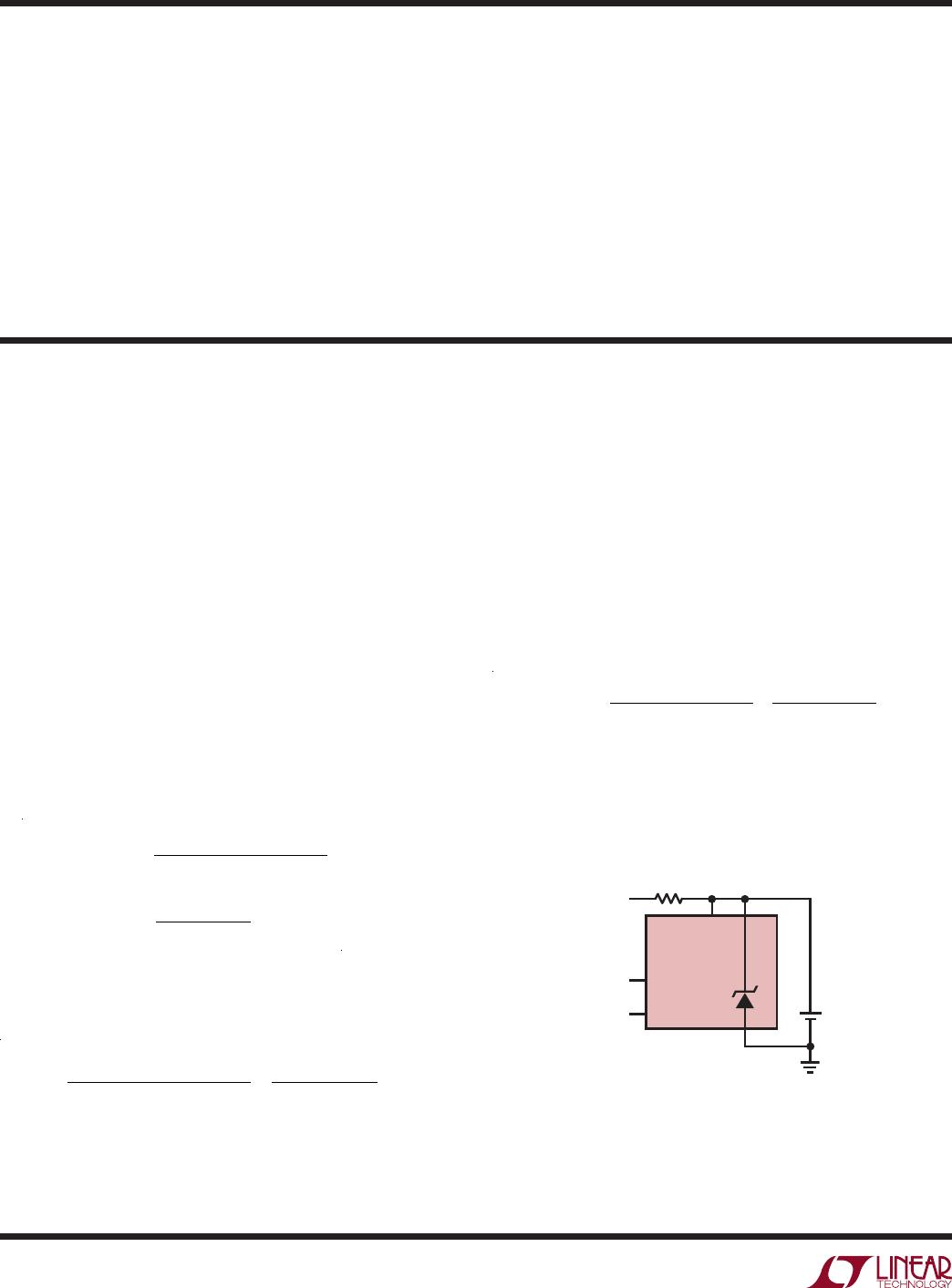
programmed level. Its shunt architecture requires just
one resistor between the input supply and the battery to
handle a wide range of battery applications. When the
input supply is removed and the battery voltage is below
the high battery output threshold, the LTC4070 consumes
just 450nA from the battery.
While the battery voltage is below the programmed float
voltage, the charge rate is determined by the input voltage,
the battery voltage, and the input resistor:
I
CHG
=
V
IN
V
BAT
( )
R
IN
As the battery voltage approaches the float voltage, the
LTC4070 shunts current away from the battery thereby
reducing the charge current. The LTC4070 can shunt up to
50mA with float voltage accuracy of ±1% over temperature.
The shunt current limits the maximum charge current, but
the 50mA internal capability can be increased by adding
an external P-channel MOSFET.
Adjustable Float Voltage, V
FLOAT
A built-in 3-state decoder connected to the ADJ pin provides
three programmable float voltages: 4.0V, 4.1V, or 4.2V.
The float voltage is programmed to 4.0V when ADJ is tied
to GND, 4.1V when ADJ is floating, and 4.2V when ADJ
is tied to V
CC
. The state of the ADJ pin is sampled about
once every 1.5 seconds. When it is being sampled, the
LTC4070 applies a relatively low impedance voltage at the
ADJ pin. This technique prevents low level board leakage
from corrupting the programmed float voltage.
NTC Qualified Float Voltage, DV
FLOAT(NTC)
The NTC pin voltage is compared against an internal
resistor divider tied to the NTCBIAS pin. This divider
has tap points that are matched to the NTC thermistor
resistance/temperature conversion table for a Vishay
thermistor with a B
25/85
value of 3490 at temperatures of
40°C, 50°C, 60°C, and 70°C.
Battery temperature conditioning adjusts the float volt-
age down to V
FLOAT_EFF
when the NTC thermistor indi-
cates that the battery temperature is too high. For a 10k
thermistor with a B
25/85
value of 3490 such as the Vishay
NTHS0402N02N1002F, and a 10k NTCBIAS resistor, each
10°C increase in temperature above 40°C causes the float
voltage to drop by a fixed amount, DV
FLOAT(NTC)
, depend-
ing on ADJ. If ADJ is at GND, the float voltage steps down
by 50mV for each 10°C temperature increment. If ADJ
is floating, the step size is 75mV. And if ADJ is at V
CC
,
the step size is 100mV. Refer to Table 1 for the range of
V
FLOAT_EFF
programming.
Table 1. NTC Qualified Float Voltage
ADJ DV
FLOAT(NTC
) TEMPERATURE V
NTC
AS % OF NTCBIAS
V
FLOAT_
EFF
GND 50mV T < 40°C
40°C ≤ T < 50°C
50°C ≤ T < 60°C
60°C ≤ T < 70°C
70°C < T
V
NTC
> 36.5%
29.0% < V
NTC
≤ 36.5%
22.8% < V
NTC
≤ 29.0%
17.8% < V
NTC
≤ 22.8%
V
NTC
≤ 17.8%
4.000V
3.950V
3.900V
3.850V
3.800V
Float 75mV T < 40°C
40°C ≤ T < 50°C
50°C ≤ T < 60°C
60°C ≤ T < 70°C
70°C ≤ T
V
NTC
> 36.5%
29.0% < V
NTC
≤ 36.5%
22.8% < V
NTC
≤ 29.0%
17.8% < V
NTC
≤ 22.8%
V
NTC
≤ 17.8%
4.100V
4.025V
3.950V
3.875V
3.800V
V
CC
100mV T < 40°C
40°C ≤ T < 50°C
50°C ≤ T < 60°C
60°C ≤ T < 70°C
70°C ≤ T
V
NTC
> 36.5%
29.0% < V
NTC
≤ 36.5%
22.8%< V
NTC
≤ 29.0%
17.8% < V
NTC
≤ 22.8%
V
NTC
≤ 17.8%
4.200V
4.100V
4.000V
3.900V
3.800V
For all ADJ pin settings the lowest float voltage setting is
3.8V = V
FLOAT
4 DV
FLOAT(NTC)
= V
FLOAT_MIN
. This occurs
at NTC thermistor temperatures above 70°C, or if the NTC
pin is grounded.
To conserve power in the NTCBIAS and NTC resistors, the
NTCBIAS pin is sampled at a low duty cycle at the same
time that the ADJ pin state is sampled.
High Battery Status Output: HBO
The HBO pin pulls high when V
CC
rises to within V
HBTH
of
the programmed float voltage, V
FLOAT_EFF
, including NTC
qualified float voltage adjustments.
If V
CC
drops below the float voltage by more than V
HBTH
+
V
HBHY
the HBO pin pulls low to indicate that the battery is
not at full charge. The input supply current of the LTC4070
drops to less than 450nA (typ) as the LTC4070 no longer
shunts current to protect the battery. The NTCBIAS sample
clock slows to conserve power, and the DRV pin is pulled
up to V
CC
.
LTC4070
8
4070fc
operaTion
For example, if the NTC thermistor requires the float voltage
to be dropped by 100mV (ADJ = V
CC
and 0.29 V
NTCBIAS
< V
NTC
< 0.36 V
NTCBIAS
) then the HBO rising threshold
is detected when V
CC
rises past V
FLOAT
DV
FLOAT(NTC)
V
HBTH
= 4.2V – 100mV – 40mV = 4.06V. The HBO falling
threshold in this case is detected when V
CC
falls below
V
FLOAT
DV
FLOAT(NTC)
– V
HBTH
– V
HBHY
= 4.2V – 100mV
– 40mV – 100mV = 3.96V.
Low Battery Status Output: LBO
When the battery voltage drops below 3.2V, the LBO pin
pulls high. Otherwise, the LBO pin pulls low when the
battery voltage exceeds about 3.5V.
While the low battery condition persists, NTC and ADJ pins
are no longer sampled—the functions are disabled—and
total supply consumption for the LTC4070 drops to less
than 300nA (typ).
General Charging Considerations
The LTC4070 uses a different charging methodology from
previous chargers. Most Li-Ion chargers terminate the
charging after a period of time. The LTC4070 does not have
a discrete charge termination. Extensive measurements
on Li-Ion cells show that the cell charge current drops to
nanoamps with the shunt charge control circuit effectively
terminating the charge. For long cell life, operate the charger
at 100mV lower charge voltage normally used.
The simplest application of the LTC4070 is shown in
Figure 1. This application requires only an external resis-
tor to program the charge/shunt current. Assume the wall
adapter voltage (V
WALL
) is 12V and the minimum battery
voltage (V
BAT_MIN
) is 3V, then the maximum charge cur-
rent is calculated as:
I
MAX _ CHARGE
=
V
WALL
V
BAT _ MIN
(
)
R
IN
=
12V 3V
(
)
162
Ω
= 55.5mA
Care must be taken in selecting the input resistor. Power
dissipated in R
IN
under full charge current is given by the
following equation:
P
DISS
=
V
WALL
V
BAT _ MIN
(
)
2
R
IN
=
12V 3V
(
)
2
162Ω
= 0.5W
The charge current decreases as the battery voltage
increases. If the rising battery voltage is 40mV less than
the programmed float voltage, the LTC4070 consumes
only 450nA of current, and all of the input current flows
into the battery. As the battery voltage reaches the
float voltage, the LTC4070 shunts current from the wall
adapter and regulates the battery voltage to V
FLOAT
. The
more shunt current the LTC4070 sinks, the less charge
current the battery gets. Eventually, the LTC4070 shunts
all the current from the battery; up to the maximum shunt
current. The maximum shunt current in this case, with no
NTC adjustment, is determined by the input resistor and
is calculated as:
I
SHUNT _ MAX
=
V
WALL
V
FLOAT
(
)
R
IN
=
12V 4.1V
(
)
162Ω
= 49mA
At this point the power dissipated in the input resistor is
388mW.
Figure 1. Single-Cell Battery Charger
4070 F01
LTC4070
ADJ
R
IN
162Ω
0.5W
GND
12V WALL
ADAPTER
Li-Ion
BATTERY
NTCBIAS
FLOAT
IF NOT NEEDED
FLOAT
NTC
V
CC
+
applicaTions inForMaTion
LTC4070
9
4070fc
applicaTions inForMaTion
Figure 3. 2-Cell Battery Charger
Figure 4. 2-Cell Battery Charger with Boosted Drive
LTC4070
ADJ
R
IN
GND
WALL
ADAPTER
FLOAT
IF NOT NEEDED
FLOAT
FLOAT
IF NOT NEEDED
FLOAT
Li-Ion
BATTERY
NTCBIAS
NTC
V
CC
V
CC1
+
4070 F03
LTC4070
ADJ
GND
Li-Ion
BATTERY
NTCBIAS
NTC
V
CC
V
CC2
+
LTC4070
ADJ
R
IN
GND
WALL
ADAPTER
FLOAT
IF NOT NEEDED
FLOAT
FLOAT
IF NOT NEEDED
FLOAT
Li-Ion
BATTERY
NTCBIAS DRV
Q1
NTC
V
CC
V
CC1
V
CC2
+
4070 F04
LTC4070
ADJ
GND
Li-Ion
BATTERY
NTCBIAS
Q1, Q2: Si3469DV
DRV
Q2
NTC
V
CC
+
Figure 2. Single-Cell Charger with Boosted Drive
4070 F02
LTC4070
ADJ
Q1: FDN352AP
R
IN
110Ω
4W
GND
24V WALL
ADAPTER
Li-Ion
BATTERY
NTCBIAS DRV
Q1
NTC
V
CC
+
FLOAT
IF NOT NEEDED
Figure 2 shows a charge circuit that can boost the charge
current as well as the shunt current with an external
P-channel MOSFET, Q1. In this case, if the wall adapter
voltage (V
WALL
) is 24V and the minimum battery voltage
(V
BAT
) is 3V, then the initial charge current is set to 191mA
by selecting R
IN
= 110Ω. Note that this resistor dissipates
over 4W of power, so select the resistor taking power rating
into account. When the battery voltage reaches the float
voltage, the LTC4070 and the external P-channel MOSFET
begin to shunt current from the wall adapter. Eventually,
the LTC4070 and the external P-channel MOSFET shunts
all available current (182mA) and no current flows to the
battery. Take the full shunt current and power into account
when selecting the external MOSFET.
The LTC4070 can also be used to regulate series-connected
battery stacks as illustrated in Figures 3 and 4. Here two
LTC4070 devices are used to charge two batteries in series;
with or without boosted drive. A single resistor sets the
maximum charge/shunt current. The GND pin of the top
device is simply connected to the V
CC
pin of the bottom
device. Care must be taken in observing the status output
pins of the top device as these signals are not ground ref-
erenced. Also, the wall adapter must have a high enough
voltage rating to charge both cells.
NTC Protection
The LTC4070 measures battery temperature with a negative
temperature coefficient thermistor thermally coupled to the
battery. NTC thermistors have temperature characteristics
which are specified in resistance-temperature conversion
tables. Internal NTC circuitry protects the battery from
excessive heat by reducing the float voltage for each
10°C rise in temperature above 40°C (assuming a Vishay
thermistor with a B
25/85
value of 3490).
The LTC4070 uses a ratio of resistor values to measure
battery temperature. The LTC4070 contains an internal fixed
resistor voltage divider from NTCBIAS to GND with four tap
points; NTC
TH1
-NTC
TH4
. The voltages at these tap points
are periodically compared against the voltage at the NTC
pin to measure battery temperature. To conserve power,
the battery temperature is measured periodically by biasing
the NTCBIAS pin to V
CC
about once every 1.5 seconds.

LTC4070EDDB#TRMPBF

Mfr. #:
Manufacturer:
Analog Devices / Linear Technology
Description:
Battery Management Simple Low-IQ Battery Charger/Protector with NTC Thermistor Input
Lifecycle:
New from this manufacturer.
Delivery:
DHL FedEx Ups TNT EMS
Payment:
T/T Paypal Visa MoneyGram Western Union