© 2009 Microchip Technology Inc. Preliminary DS22131C-page 1
25LC080C 25LC320A
25LC080D 25LC640A
25LC160C 25LC128
25LC160D 25LC256
Features:
• Max. Clock 5 MHz
• Low-power CMOS Technology:
- Max. Write Current: 5 mA at 5.5V, 5 MHz
- Read Current: 5 mA at 5.5V, 5 MHz
- Standby Current: 10 μA at 5.5V
• 1024 x 8 through 32768 x 8-bit Organization
• Byte and Page-level Write Operations
• Self-timed Erase and Write Cycles (6 ms max.)
• Block Write Protection:
- Protect none, 1/4, 1/2 or all of array
• Built-in Write Protection:
- Power-on/off data protection circuitry
- Write enable latch
- Write-protect pin
• Sequential Read
• High Reliability:
- Endurance: >1M erase/write cycles
- Data retention: > 200 years
- ESD protection: > 4000V
• Temperature Range Supported:
• Package is Pb-free and RoHS Compliant
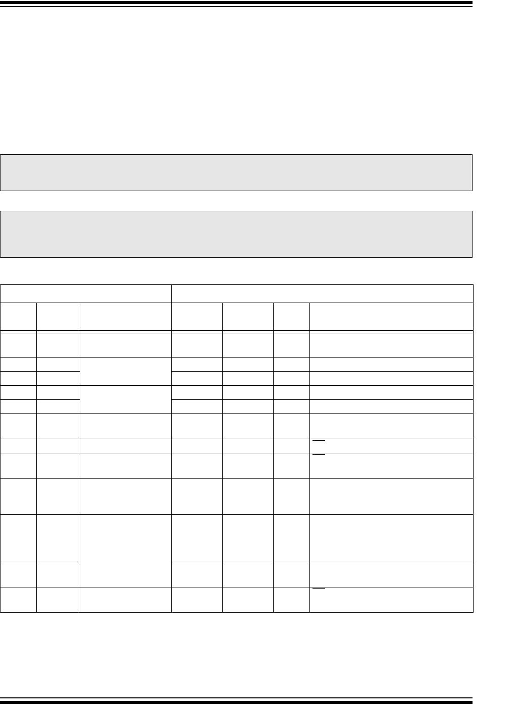
Pin Function Table
Description:
Microchip Technology Inc. 25LCXXX* devices are Mid-
density 8 through 256 Kbit Serial Electrically Erasable
PROMs (EEPROM). The devices are organized in
blocks of x8-bit memory and support the Serial Periph-
eral Interface (SPI) compatible serial bus architecture.
Byte-level and page-level functions are supported.
The bus signals required are a clock input (SCK) plus
separate data in (SI) and data out (SO) lines. Access to
the device is controlled through a Chip Select (CS
)
input.
Communication to the device can be paused via the
hold pin (HOLD
). While the device is paused, transi-
tions on its inputs will be ignored, with the exception of
Chip Select, allowing the host to service higher priority
interrupts.
The 25LCXXX is available in a standard 8-lead SOIC
package. The package is Pb-free.
Package Types (not to scale)
- Extended (H): -40°C to +150°C
Name Function
CS
Chip Select Input
SO Serial Data Output
WP
Write-Protect
V
SS Ground
SI Serial Data Input
SCK Serial Clock Input
HOLD
Hold Input
V
CC Supply Voltage
CS
SO
WP
V
SS
1
2
3
4
8
7
6
5
V
CC
HOLD
SCK
SI
SOIC
(SN)
8K-256K SPI Serial EEPROM High Temp Family Data Sheet
*25LCXXX is used in this document as a generic part number for the 25 series devices.