© 2009 Microchip Technology Inc. Preliminary DS22131C-page 13
25LCXXX
3.6 Write Status Register Instruction
(WRSR)
The Write Status Register instruction (WRSR) allows the
user to write to the nonvolatile bits in the STATUS
register as shown in Table 3-2. The user is able to
select one of four levels of protection for the array by
writing to the appropriate bits in the STATUS register.
The array is divided up into four segments. The user
has the ability to write-protect none, one, two or all four
of the segments of the array. The partitioning is
controlled as shown in Table 3-3.
The Write-Protect Enable (WPEN) bit is a nonvolatile
bit that is available as an enable bit for the WP
pin. The
Write-Protect (WP
) pin and the Write-Protect Enable
(WPEN) bit in the STATUS register control the
programmable hardware write-protect feature. Hard-
ware write protection is enabled when WP
pin is low
and the WPEN bit is high. Hardware write protection is
disabled when either the WP
pin is high or the WPEN
bit is low. When the chip is hardware write-protected,
only writes to nonvolatile bits in the STATUS register
are disabled. See Table 5-1 for a matrix of functionality
on the WPEN bit.
See Figure 3-7 for the WRSR timing sequence.
TABLE 3-3: ARRAY PROTECTION
TABLE 3-4: ARRAY PROTECTED ADDRESS LOCATIONS
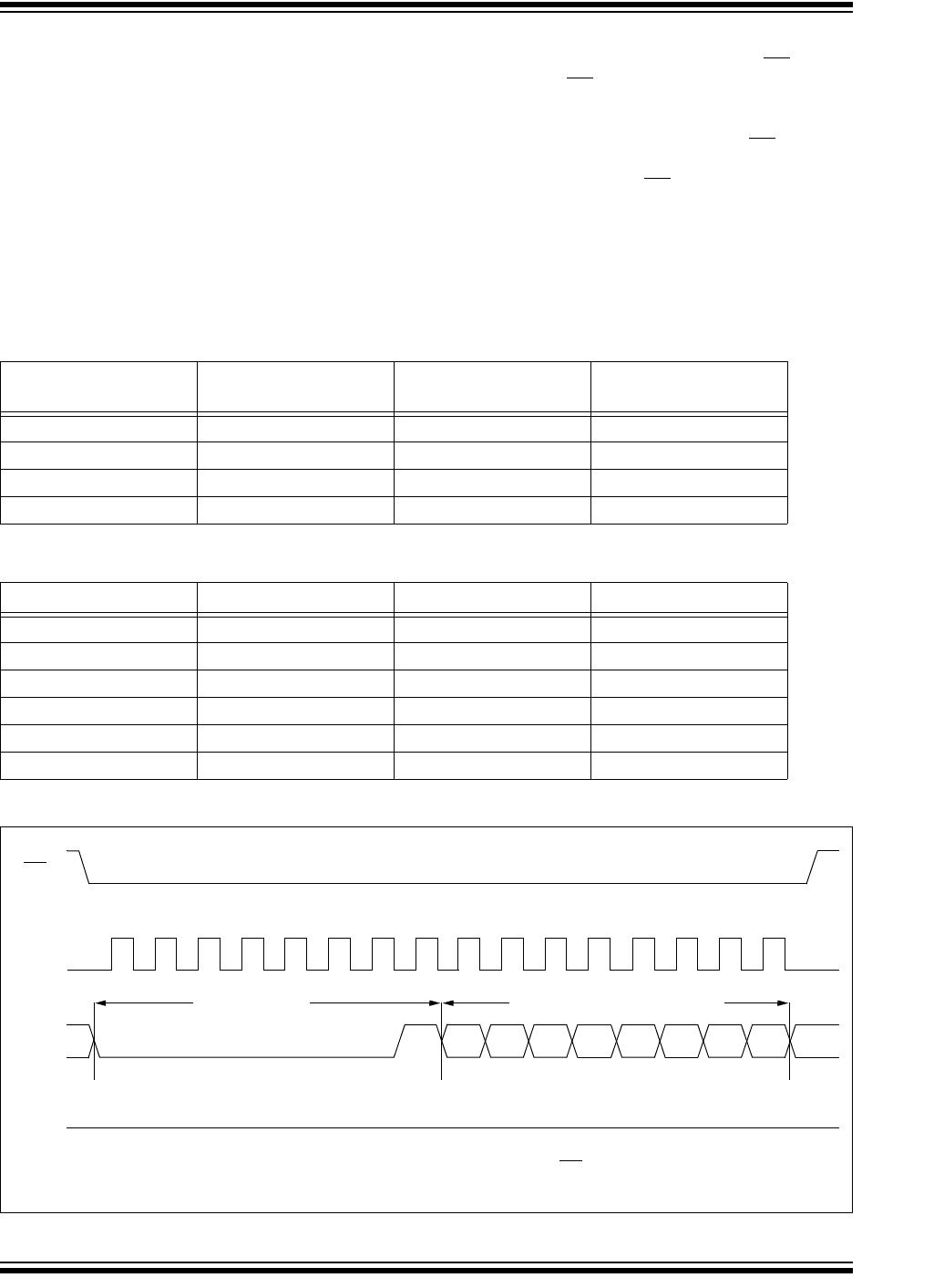
FIGURE 3-7: WRITE STATUS REGISTER TIMING SEQUENCE (WRSR)
BP1 BP0
Array Addresses
Write-Protected
Array Addresses
Unprotected
00
None All
01
Upper 1/4 Lower 3/4
10
Upper 1/2 Lower 1/2
11
All None
Density Upper 1/4 Upper 1/2 All
8K 300h - 3FFh
200h - 3FFh 000h - 3FFh
16K 600h - 7FFh
400h - 7FFh 000h - 7FFh
32K C00h - FFFh
800h - FFFh 000h - FFFh
64K 1800h - 1FFFh
1000h - 1FFFh 0000h - 1FFFh
128K 3000h - 3FFFh
2000h - 3FFFh 0000h - 3FFFh
256K 6000h - 7FFFh
4000h - 7FFFh 0000h - 7FFFh
SO
SI
CS
9101112131415
0 1000000
7654
210
Instruction Data to STATUS Register
High-Impedance
SCK
0 2345671
8
3
Note: An internal write cycle (TWC) is initiated on the rising edge of CS after a valid write STATUS register
sequence.
25LCXXX
DS22131C-page 14 Preliminary © 2009 Microchip Technology Inc.
4.0 DATA PROTECTION
The following protection has been implemented to
prevent inadvertent writes to the array:
The write enable latch is reset on power-up
A write enable instruction must be issued to set
the write enable latch
After a byte write, page write or STATUS register
write, the write enable latch is reset
•CS
must be set high after the proper number of
clock cycles to start an internal write cycle
Access to the array during an internal write cycle
is ignored and programming is continued
5.0 POWER-ON STATE
The 25LCXXX powers on in the following state:
The device is in low-power Standby mode
(CS= 1)
The write enable latch is reset
SO is in high-impedance state
A high-to-low-level transition on CS
is required to
enter active state
TABLE 5-1: WRITE-PROTECT FUNCTIONALITY MATRIX
WEL
(SR bit 1)
WPEN
(SR bit 7)
WP
(pin 3)
Protected Blocks Unprotected Blocks STATUS Register
0xxProtected Protected Protected
10xProtected Writable Writable
110 (low) Protected Writable Protected
111 (high) Protected Writable Writable
x = don’t care
© 2009 Microchip Technology Inc. Preliminary DS22131C-page 15
25LCXXX
6.0 PACKAGING INFORMATION
6.1 Package Marking Information
Note: Custom marking available.
8-Lead SOIC
XXXXYYWW
XXXXXXXT
NNN
Example:
SN 0728
25LC32AH
1L7
Legend: XX...X Customer-specific information
Y Year code (last digit of calendar year)
YY Year code (last 2 digits of calendar year)
WW Week code (week of January 1 is week ‘01’)
NNN Alphanumeric traceability code
Pb-free JEDEC designator for Matte Tin (Sn)
* This package is Pb-free. The Pb-free JEDEC designator ( )
can be found on the outer packaging for this package.
Note: In the event the full Microchip part number cannot be marked on one line, it will
be carried over to the next line, thus limiting the number of available
characters for customer-specific information.
3
e
3
e
3
e
8-Lead SOIC Package Marking (Pb-Free)
Device Line 1 Marking
25LC080C 25LC80CT
25LC080D 25LC80DT
25LC160C 25LC16CT
25LC160D 25LC16DT
25LC320A 25LC32AT
25LC640A 25L640AT
25LC128 25LC128T
25LC256 25LC256T
Note 1: T = Temperature Grade (H).

25LC256T-H/SN

Mfr. #:
Manufacturer:
Microchip Technology
Description:
EEPROM 256K, 32K X 8, 2.5V SER EE 150C
Lifecycle:
New from this manufacturer.
Delivery:
DHL FedEx Ups TNT EMS
Payment:
T/T Paypal Visa MoneyGram Western Union