MAX2120
Complete, Direct-Conversion Tuner for DVB-S
and Free-to-Air Applications
8 _______________________________________________________________________________________
Pin Description
PIN NAME FUNCTION
1 VCC_RF2
DC Power Supply for LNA. Connect to a +3.3V low-noise supply. Bypass to GND with a 1nF capacitor
connected as close as possible to the pin. Do not share capacitor ground vias with other ground
connections.
2 VCC_RF1
DC Power Supply for LNA. Connect to a +3.3V low-noise supply. Bypass to GND with a 1nF capacitor
connected as close as possible to the pin. Do not share capacitor ground vias with other ground
connections.
3 GND Ground. Connect to the board’s ground plane for proper operation.
4 RFIN Wideband 75Ω RF Input. Connect to an RF source through a DC-blocking capacitor.
5 GC1
RF Gain-Control Input. High-impedance analog input, with a 0.5V to 2.7V operating range. V
GC1
=
0.5V corresponds to the maximum gain setting.
6 VCC_LO
DC Power Supply for LO Generation Circuits. Connect to a +3.3V low-noise supply. Bypass to GND
with a 1nF capacitor connected as close as possible to the pin. Do not share capacitor ground vias
with other ground connections.
7 VCC_VCO
DC Power Supply for VCO Circuits. Connect to a +3.3V low-noise supply. Bypass to GND with a 1nF
capacitor connected as close as possible to the pin. Do not share capacitor ground vias with other
ground connections.
8 VCOBYP
Internal VCO Bias Bypass. Bypass to GND with a 100nF capacitor connected as close as possible to
the pin. Do not share capacitor ground vias with other ground connections.
9 VTUNE
High-Impedance VCO Tune Input. Connect the PLL loop filter output directly to this pin with as short
of a connection as possible.
10 GNDTUNE Ground for VTUNE. Connect to the PCB ground plane.
11 GNDSYN Ground for Synthesizer. Connect to the PCB ground plane.
12 CPOUT
Charge-Pump Output. Connect this output to the PLL loop filter input with the shortest connection
possible.
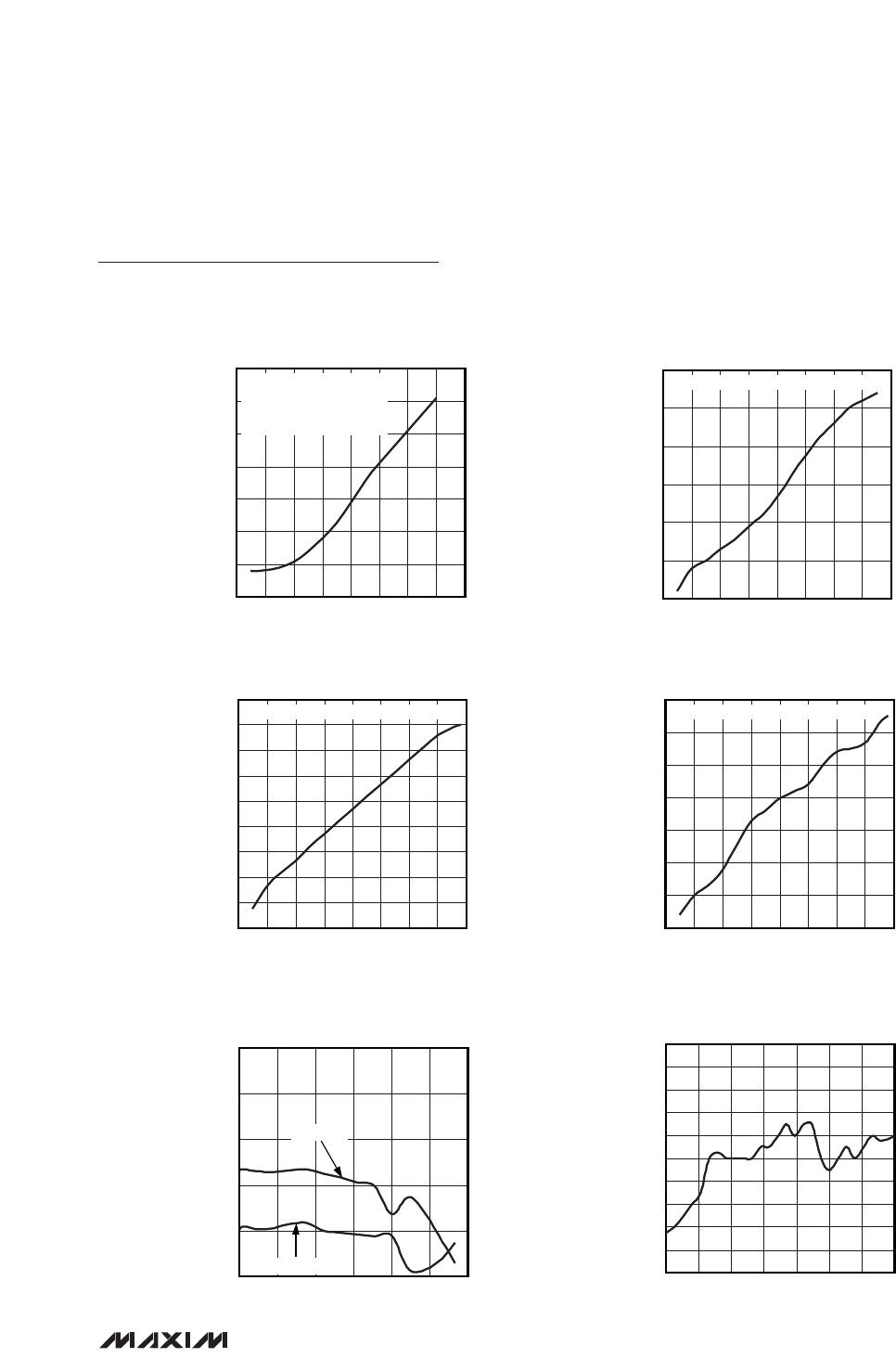
Typical Operating Characteristics (continued)
(MAX2120 Evaluation Kit: V
CC
= +3.3V, baseband output frequency = 5MHz; V
GC1
= 1.2V; T
A
= +25°C. Default register settings
except BBG[3:0] = 1011.)
PHASE NOISE vs. OFFSET FREQUENCY
MAX2120 toc19
OFFSET FREQUENCY (kHz)
PHASE NOISE (dBc/Hz)
100110
-100
-90
-70
-60
-130
-110
-80
-120
0.1 1000
f
LO
= 1800MHz
LO LEAKAGE vs. LO FREQUENCY
MAX2120 toc20
LO FREQUENCY (MHz)
LO LEAKAGE (dBm)
19251175 16751425
-80
-70
-90
-85
-75
925 2175
MEASURED AT RF INPUT