22
LTC1562
1562fa
APPLICATIONS INFORMATION
WUU
U
The configuration is robust against tolerances in the C
IN1
value when
f
N
approaches f
0
(for f
N
/f
0
1.4, as a rule of
thumb) which is attractive in narrow transition-band fil-
ters, because of the relative cost of high accuracy capaci-
tors. Further application details appear in Part 1 of the
series of articles.
Feedforward Notches for f
N
< f
0
Just as feedforward around an inverting bandpass section
yields a notch at the section’s f
0
(Figure 11 with C
IN1
= 0),
feedforward around an inverting lowpass section causes
a notch at zero frequency (which is to say, a highpass
response). Moreover, and this is what makes it useful,
introducing a capacitor for phase lead moves the notch
frequency up from DC, exactly as C
IN1
in Figure 11 moves
the notch frequency up from the center frequency f
0
. In
Figure 14, the inverting lowpass output (V2) of the Opera-
tional Filter block is summed, at a virtual ground, with a
fed-forward input signal. Capacitor C
IN1
shifts the result-
ing notch frequency, f
N
, up from zero, giving a low
frequency notch with a highpass shape (Figure 15). The
H
BR
(s) response parameters are now:
ƒ=ƒ
=
NO
QININ
N
GAIN
FF
R
R
C
C
R
R
H
R
R
1
121
111
2
The constraint required for exact cancellation of the two
paths (i.e., for infinite notch depth) becomes:
R
R
RC
RC
IN
FF
QIN2
2
11
1
=
R1 and C are the internal precision components (in the
LTC1562, 10k and 159pF respectively) as described above
in Setting f
0
and Q.
The configuration of Figure 14 is most useful as a lower
stopband notch in a bandpass filter, because the resistors
R
IN2
and R
FF2
can replace the input resistor R
IN
of a
bandpass section made from a second Operational Filter
block, as in Figure 6a. The configuration is robust against
tolerances in the C
IN1
value when f
N
approaches f
0
(for f
0
/
f
N
1.4, as a rule of thumb) which is attractive in narrow
transition-band filters, because of the relative cost of high
accuracy capacitors. Further application details appear in
Part 2 of the series of articles.
FREQUENCY (Hz)
10k
–60
GAIN (dB)
–40
–20
20
100k 1M
1562 F15
0
f
O
= 100kHz
f
N
= 50kHz
Q = 1
HIGH FREQ GAIN = 0dB
f
N
2
f
O
2
DC GAIN = H
N
()
HIGH FREQ
GAIN = H
N
Figure 15. Notch Response with f
N
< f
0
Figure 14. Feedforward Notch Configuration for f
N
< f
O
INV V1
2nd ORDER
1/4 LTC1562
V2
R21R
Q1
R
IN1
R
IN2
R
GAIN
I
O
R
FF2
C
IN1
V
IN
V
OUT
1562 F14
VIRTUAL
GROUND
+
23
LTC1562
1562fa
R-C Universal Notches
A different way to get 180° phase shift for a notch is to use
the built-in 90° phase difference between the two Opera-
tional Filter block outputs along with a further 90° from an
external capacitor. This method achieves deep notches
independent of component matching, unlike the previous
techniques, and it is convenient for cascaded highpass as
well as lowpass and bandpass filters.
The V2 output of an Operational Filter block is a time-
integrated version of V1 (see Figure 3), and therefore lags
V1 by 90° over a wide range of frequencies. In Figure 16,
a notch response occurs when a 2nd order section drives
a virtual-ground input through two paths, one through a
capacitor and one through a resistor. Again, the virtual
ground may come from an op amp as shown, or from
another Operational Filter block’s INV input. Capacitor C
N
adds a further 90° to the 90° difference between V1 and
V2, producing a wideband 180° phase difference, but
frequency-dependent amplitude ratio, between currents
I
R
and I
C
. At the frequency where I
R
and I
C
have equal
magnitude, I
O
becomes zero and a notch occurs. This
gives a net transfer function from V
IN
to V
OUT
in the form
of H
BR
(s) as above, with parameters:
ƒ=
π
=
N
NN
N
GAIN
IN
N
RCRC
H
R
R
C
C
1
21
1
APPLICATIONS INFORMATION
WUU
U
DCGain
R
R
R
R
High Frequency Gain
DCGain
RC
RC
GAIN
IN N
O
N
NN
=
ƒ
ƒ
==
1
2
2
21
21
R1 and C are the internal precision components (in the
LTC1562, 10k and 159pF respectively) as described above
in Setting f
0
and Q.
Unlike the notch methods of Figures 11 and 14, notch
depth from Figure 16 is inherent, not derived from compo-
nent matching. Errors in the R
N
or C
N
values alter the notch
frequency, f
N
, rather than the degree of cancellation at f
N
.
Also, the notch frequency, f
N
, is independent of the section’s
center frequency f
0
, so f
N
can freely be equal to, higher
than or lower than f
0
(Figures 12, 13 or 15, respectively)
without changing the configuration. The chief drawback of
Figure 16 compared to the previous methods is a very
practical onethe C
N
capacitor value directly scales H
N
(and therefore the high frequency gain). Capacitor values
are generally not available in increments or tolerances as
fine as those of resistors, and this configuration lacks the
property of the previous two configurations that sensitiv-
ity to the capacitor value falls as f
N
approaches f
0
. Unlike
the previous notch circuits, this one is also noninverting at
DC.
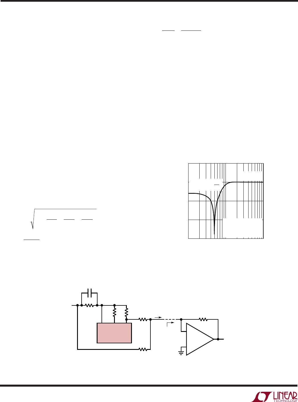
Figure 16. The R-C Universal Notch Configuration for an Operational Filter Block
INV V1
2nd ORDER
1/4 LTC1562
V2
R21
R
Q1
R
IN1
R
N
R
GAIN
I
O
C
N
V
IN
V
OUT
1562 F16
VIRTUAL
GROUND
+
I
R
I
C
24
LTC1562
1562fa
TYPICAL APPLICATIONS
U
(Advanced)
R
Q1
30.1k
R
Q3
34k
R
IN3
31.6k
R
IN1
48.7k
V
IN
R
Q2
13k
R
IN2
37.4k
R
IN4
32.4k
C
IN2
24pF
R
Q4
11.5k
R22 57.6k
R24 32.4k
0.1µF
V
OUT
–5V5V
R21 31.6k
R23 31.6k
LTC1562
INVB
V1B
V2B
V
+
SHDN
V2A
V1A
INVA
20
19
18
16
15
13
12
11
INVC
V1C
V2C
V
AGND
V2D
V1D
INVD
1
2
3
5
6
8
9
10
0.1µF
C
IN4
10pF
1562 TA12a
C
IN3
18pF
SCHEMATIC INCLUDES PIN NUMBERS FOR 20-PIN PACKAGE.
PINS 4, 7, 14, 17 (NOT SHOWN) ALSO CONNECT TO V
8th Order 50kHz Lowpass Elliptic Filter
with 100dB Stopband Attenuation
8th Order 100kHz Elliptic Bandpass Filter
R
Q1
86.6k
R
Q3
71.5k
R
IN3
294k
C
IN3
18pF
R
IN1
95.3k
C
IN1
5.6pF
V
IN
R
Q2
84.5k
R
IN2
93.1k
R
FF2
301k
R
IN4
95.3k
R
FF4
332k
R
Q4
82.5k
R22 10k
R24 9.53k
0.1µF
V
OUT
–5V5V
R21 10.7k
R23 10k
LTC1562
INVB
V1B
V2B
V
+
SHDN
V2A
V1A
INVA
20
19
18
16
15
13
12
11
INVC
V1C
V2C
V
AGND
V2D
V1D
INVD
1
2
3
5
6
8
9
10
0.1µF
1562 F13a
SCHEMATIC INCLUDES PIN NUMBERS FOR 20-PIN PACKAGE.
PINS 4, 7, 14, 17 (NOT SHOWN) ALSO CONNECT TO V
FREQUENCY (kHz)
USES THREE R-C UNIVERSAL NOTCHES AT f
N
= 133kHz, 167kHz, 222kHz.
DETAILED DESCRIPTION IN LINEAR TECHNOLOGY DESIGN NOTE 195.
WIDEBAND OUTPUT NOISE 60µV
RMS
–120
–60
–80
–100
20
0
–20
–40
1562 TA12b
GAIN (dB)
10
500
100
Amplitude Response
Amplitude Response
FREQUENCY (kHz)
25
–90
GAIN (dB)
–70
–80
–20
–30
–40
–50
–60
–10
0
100 175
1562 TA13b
10

LTC1562CN#PBF

Mfr. #:
Manufacturer:
Analog Devices Inc.
Description:
Active Filter Active RC Quad Universal Filter
Lifecycle:
New from this manufacturer.
Delivery:
DHL FedEx Ups TNT EMS
Payment:
T/T Paypal Visa MoneyGram Western Union