10
COMMERCIAL AND INDUSTRIAL
TEMPERATURE RANGES
IDT72V51233/72V51243/72V51253 3.3V, MULTI-QUEUE FLOW-CONTROL DEVICES
(4 QUEUES) 18 BIT WIDE CONFIGURATION 589,824, 1,179,648 and 2,359,296 bits
NOTES:
1. Inputs should not change after Master Reset.
2. These pins are for the JTAG port. Please refer to pages 45-49 and Figures 27-29.
TDO
(2)
JTAG Test Data LVTTL One of four terminals required by IEEE Standard 1149.1-1990. During the JTAG boundary scan
(A9) Output OUTPUT operation, test data serially loaded output via the TDO on the falling edge of TCK from either the Instruction
Register, ID Register and Bypass Register. This output is high impedance except when shifting, while in
SHIFT-DR and SHIFT-IR controller states.
TMS
(2)
JTAG Mode Select LVTTL TMS is a serial input pin. One of four terminals required by IEEE Standard 1149.1-1990. TMS directs the
(B8) INPUT device through its TAP controller states. An internal pull-up resistor forces TMS HIGH if left unconnected.
TRST
(2)
JTAG Reset LVTTL TRST is an asynchronous reset pin for the JTAG controller. The JTAG TAP controller does not automatically
(C7) INPUT reset upon power-up, thus it must be reset by either this signal or by setting TMS= HIGH for five TCK cycles.
If the TAP controller is not properly reset then the outputs will always be in high-impedance. If the JTAG
function is used but the user does not want to use TRST, then TRST can be tied with MRS to ensure
proper queue operation. If the JTAG function is not used then this signal needs to be tied to GND. An
internal pull-up resistor forces TRST HIGH if left unconnected.
WADEN Write Address LVTTL The WADEN input is used in conjunction with WCLK and the WRADD address bus to select a queue to
(P4) Enable INPUT be written in to. A queue addressed via the WRADD bus is selected on the rising edge of WCLK provided
that WADEN is HIGH. WADEN should be asserted (HIGH) only during a queue change cycle(s). WADEN
should not be permanently tied HIGH. WADEN cannot be HIGH for the same WCLK cycle as FSTR. Note,
that a write queue selection cannot be made, (WADEN must NOT go active) until programming of the part
has been completed and SENO has gone LOW.
WCLK Write Clock LVTTL When enabled by WEN, the rising edge of WCLK writes data into the selected queue via the input bus,
(T7) INPUT Din. The queue to be written to is selected via the WRADD address bus and a rising edge of WCLK while
WADEN is HIGH. A rising edge of WCLK in conjunction with FSTR and WRADD will also select the device
to be placed on the PAFn bus during direct flag operation. During polled flag operation the PAFn bus is
cycled with respect to WCLK and the FSYNC signal is synchronized to WCLK. The PAFn, PAF and FF
outputs are all synchronized to WCLK. During device expansion the FXO and FXI signals are based on
WCLK. The WCLK must be continuous and free-running.
WEN Write Enable LVTTL The WEN input enables write operations to a selected queue based on a rising edge of WCLK. A queue
(T6) INPUT to be written to can be selected via WCLK, WADEN and the WRADD address bus regardless of the state
of WEN. Data present on Din can be written to a newly selected queue on the second WCLK cycle after
queue selection provided that WEN is LOW. A write enable is not required to cycle the PAFn bus (in polled
mode) or to select the device , (in direct mode).
WRADD Write Address Bus LVTTL For the 4Q device the WRADD bus is 5 bits. The WRADD bus is a dual purpose address bus. The first
[4:0] INPUT function of WRADD is to select a queue to be written to. The least significant 2 bits of the bus, WRADD[1:0]
(WRADD4-T1 are used to address 1 of 4 possible queues within a multi-queue device. The most significant 3 bits,
WRADD3-R1 WRADD[4:2] are used to select 1 of 8 possible multi-queue devices that may be connected in expansion
WRADD2-R2 mode. These 3 MSB’s will address a device with the matching ID code. The address present on the
WRADD1-N1 WRADD bus will be selected on a rising edge of WCLK provided that WADEN is HIGH, (note, that data
WRADD0-N2) present on the Din bus can be written into the previously selected queue on this WCLK edge and on the
next rising WCLK also, providing that WEN is LOW). Two WCLK rising edges after write queue select,
data can be written into the newly selected queue.
The second function of the WRADD bus is to select the device of queues to be loaded on to the PAFn bus
during strobed flag mode. The most significant 3 bits, WRADD[4:2] are again used to select 1 of 8 possible
multi-queue devices that may be connected in expansion mode. Address bits WRADD[1:0] are don’t care
during device selection. The device address present on the WRADD bus will be selected on the rising
edge of WCLK provided that FSTR is HIGH, (note, that data can be written into the previously selected
queue on this WCLK edge). Please refer to Table 1 for details on the WRADD bus.
VCC (See Pin +3.3V Supply Power These are VCC power supply pins and must all be connected to a +3.3V supply rail.
table for details)
GND (See Pin Ground Pin Ground These are Ground pins and must all be connected to the GND supply rail.
table for details)
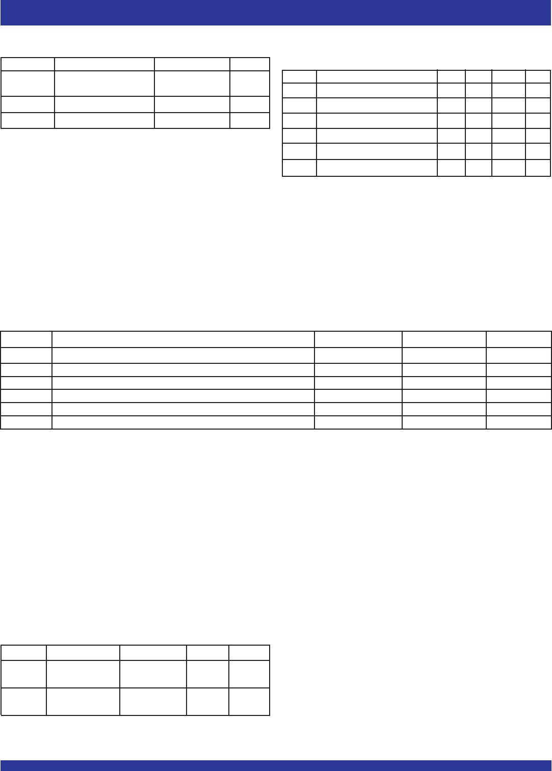
PIN DESCRIPTIONS (CONTINUED)
Symbol & Name I/O TYPE Description
Pin No.
**Please continue to next page for Pin Number Table.