ISL6730A, ISL6730B, ISL6730C, ISL6730D
6
FN8258.1
August 8, 2013
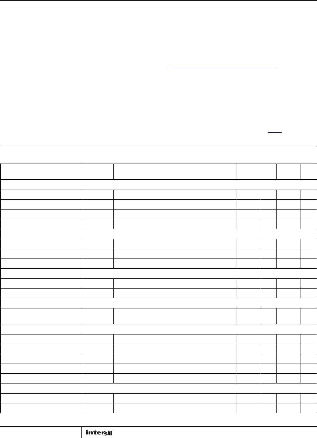
Absolute Maximum Ratings Thermal Information
VCC to GND. . . . . . . . . . . . . . . . . . . . . . . . . . . . . . . . . . . . . . . . . . -0.3V to +28V
GATE to GND. . . . . . . . . . . . . . . . . . . . . . . . . . . . . . . . . . . . . . . . . . . . . -0.3V to +18V
VIN, BO, ISEN, FB and COMP to GND. . . . . . . . . . . . . . . . . . . . . . . .-0.3V to +6.3V
ESD Rating
Human Body Model (Tested per JESD22-A114) . . . . . . . . . . . . . . .2.5kV
Machine Model (Tested per JESD22-A115). . . . . . . . . . . . . . . . . . . . 200V
Charged Device Model (Tested per JESD-C101E. . . . . . . . . . . . . . . . . 1kV
Latch Up (Tested per JESD-78B; Class 2, Level A) . . . . . . . . . . . . . . 100mA
Recommended Operating Conditions
VCC to GND. . . . . . . . . . . . . . . . . . . . . . . . . . . . . . . . . . . . . . . . . . 15V to + 20V
Ambient Temperature Range . . . . . . . . . . . . . . . . . . . . . . .-40°C to +125°C
Thermal Resistance (Typical) θ
JA
(°C/W) θ
JC
(°C/W)
MSOP Package (Notes 4, 5) . . . . . . . . . . . . 136.9 39.4
Maximum Junction Temperature (Plastic Package) . . . . . . . . . . . .+150°C
Maximum Storage Temperature Range . . . . . . . . . . . . . .-65°C to +150°C
Ambient Temperature Range . . . . . . . . . . . . . . . . . . . . . . .-40°C to +125°C
Junction Temperature Range . . . . . . . . . . . . . . . . . . . . . . .-40°C to +125°C
Pb-Free Reflow Profile . . . . . . . . . . . . . . . . . . . . . . . . . . . . . . . see link below
http://www.intersil.com/pbfree/Pb-FreeReflow.asp
CAUTION: Do not operate at or near the maximum ratings listed for extended periods of time. Exposure to such conditions may adversely impact product
reliability and result in failures not covered by warranty.
NOTES:
4. θ
JA
is measured with the component mounted on a high effective thermal conductivity test board in free air. See Tech Brief TB379 for details.
5. For θ
JC
, the "case temp" location is taken at the package top center.
Electrical Specifications Operating Conditions: V
CC
= 15V, T
A
= +25°C. Boldface limits apply over the operating temperature range,
-40°C to +125°C.
PARAMETER SYMBOL TEST CONDITIONS
MIN
(Note 8) TYP
MAX
(Note 8) UNITS
V
CC
SUPPLY CURRENT
Start Up Current I
START
V
FB
= 1V, V
CC
< V
CC
(ON) 73 106 139 µA
Standby Current I
STDN
V
FB
= GND, V
CC
> V
CC
(ON) 179 237 295 µA
Skip Mode Current I
CCSKIP
V
FB
= 2.5V, COMP = SKIP*0.25 +1V 580 690 800 µA
Operating Current (Note 6) I
CC
GATE is floating 3.0 3.7 4.2 mA
VCC UVLO
UVLO Rising Threshold V
CC(ON)
91011V
UVLO Falling Threshold V
CC(OFF)
6.7 7.5 8.3 V
UVLO Threshold Hysteresis V
CC(HYS)
-2.5- V
REGULATOR VOLTAGE VREG
Overall Accuracy V
REG
I
REG
= 0 to -10mA, V
CC
= 15V, Load Capacitor = 47nF 5.1 5.4 5.6 V
Current Limit 30 50 70 mA
PWM CONVERTERS
Maximum Duty Cycle f
SW
= 124kHz for ISL6730A/C and
f
SW
= 62kHz for ISL6730B/D
94.8 96.5 - %
OSCILLATOR
Free Running Frequency, ISL6730A/C T
A
= -40°C to +125°C, V
IN
= 0.6V 98 107 116 kHz
Free Running Frequency, ISL6730A/C T
A
= -40°C to +125°C, V
IN
= 2.5V 114 125 136 kHz
Free Running Frequency, ISL6730B/D T
A
= -40°C to +125°C, V
IN
= 0.6V 47 54 61 kHz
Free Running Frequency, ISL6730B/D T
A
= -40°C to +125°C, V
IN
= 2.5V 57 64 71 kHz
PWM Ramp Amplitude V
m
1.33 1.46 1.59 V
GATE DRIVER
Gate Drive Pull-Down Resistance V
CC
= 15V, I
GATE
= 15mA - 2.33 4.46 Ω
Gate Drive Pull-Up Voltage Drop V
CC
= 9V, I
GATE
= 15mA 0.15 0.3 0.45 V