Expand menu
Hello, Sign in
My Account
0
Cart
Home
Products
Sensors
Semiconductors
Passive Components
Connectors
Power
Electromechanical
Optoelectronics
Circuit Protection
Integrated Circuits - ICs
Main Products
Manufacturers
Blog
Services
About OMO
About Us
Contact Us
Check Stock
LTC2872IUHF#PBF
P1-P3
P4-P6
P7-P9
P10-P12
P13-P15
P16-P18
P19-P21
P22-P24
P25-P27
P28-P28
L
TC2872
22
2872f
Typical applicaTions
Figure 20. L
TC2872 in V
arious Basic Port Configurations
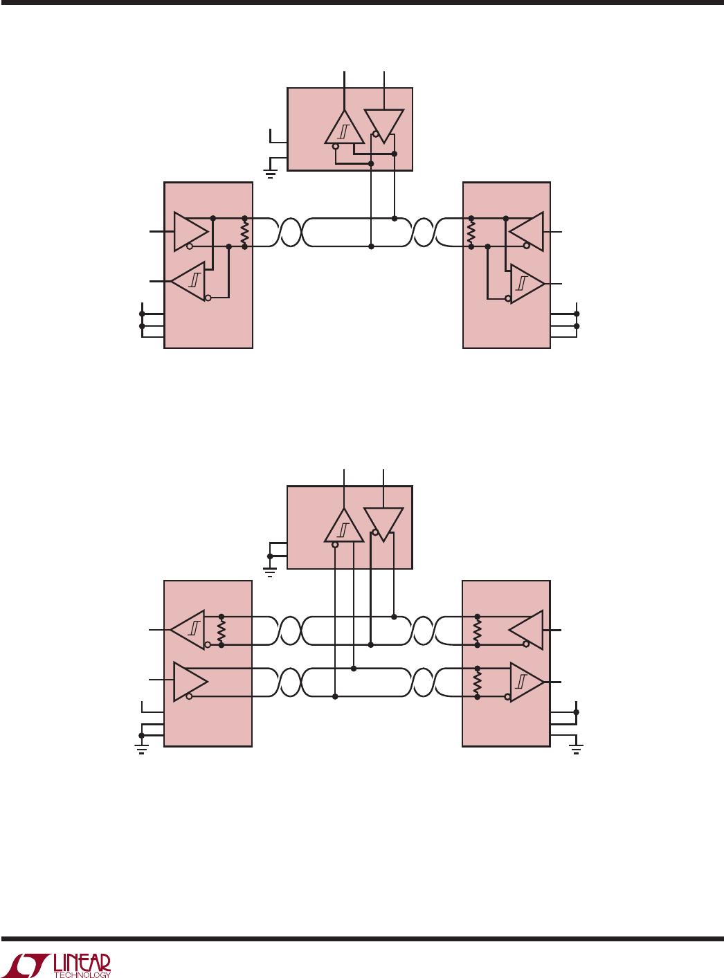
Figure 21. Loopback in
RS232 and RS485 Modes
Figure 22. Half-Duplex RS485
Mode with Driver and Receiver Line
T
ermination on Each Port
Figure 23. Full-Duplex RS485 Mode
with Driver and Receiver Line
T
ermination on Port 1, and Receiver
-
Only T
ermination on Port 2
V
L
DY1
DZ1
Y1
Z1
RA1
RB1
A1
B1
DY2
Y2
Z2
RA2
A2
B2
2872 F21
L
TC2872
LB
485/
232
_2
485/
232
_1
RXEN1
RXEN2
H/
F
GND
V
L
2872 F22
L
TC2872
H/
F
TE485_1
TE485_2
485/
232
_1
485/
232
_2
DZ1
DZ2
LB
GND
DY1
120Ω
Y1
Z1
RA1
A1
B1
120Ω
DY2
120Ω
Y2
Z2
RA2
A2
B2
120Ω
V
L
2872 F23
L
TC2872
TE485_1
TE485_2
DZ1
485/
232
_1
485/
232
_2
DZ2
H/
F
LB
GND
DY2
Y2
Z2
RA2
A2
B2
120Ω
DY1
Y1
Z1
RA1
A1
B1
120Ω
120Ω
V
CC
= 3V to 5.5V
, V
L
= 1.7V to V
CC
. Logic input pins not shown are tied to a valid logic
state. External components necessary for operation are not shown.
2872 F20
485/
232
_1
485/
232
_2
LB
DY1
DZ1
Y1
Z1
RA1
RB1
A1
B1
DY2
DZ2
Y2
Z2
RA2
RB2
A2
B2
L
TC2872
POR
T 1: RS232
POR
T 2: RS232
POR
T 1: RS232
POR
T 2: RS485
POR
T 1: RS485
POR
T 2: RS232
POR
T 1: RS485
POR
T 2: RS485
DY1
DZ1
Y1
Z1
RA1
RB1
A1
B1
DY2
Y2
Z2
RA2
A2
B2
L
TC2872
485/
232
_2
485/
232
_1
H/
F
LB
GND
DY2
DZ2
Y2
Z2
RA2
RB2
A2
B2
DY1
Y1
Z1
RB1
A1
B1
L
TC2872
485/
232
_1
485/
232
_2
H/
F
LB
GND
DY1
V
L
V
L
V
L
Y1
Z1
RA1
A1
B1
L
TC2872
485/
232
_1
485/
232
_2
H/
F
LB
GND
DY2
Y2
Z2
RA2
A2
B2
L
TC2872
23
2872f
Typical applicaTions
Figure 24. T
ypical RS485 Half Duplex Network
2872 F25
½ L
TC2872
MASTER
120Ω
½ L
TC2872
½ L
TC2872
SLA
VE
TE485
H/
F
TE485
DZ
H/
F
TE485
DZ
H/
F
V
L
V
L
120Ω
120Ω
Figure 25. T
ypical RS485 Full Duplex Network
2872 F24
½ L
TC2872
120Ω
½ L
TC2872
½ L
TC2872
TE485
H/
F
TE485
DZ
H/
F
TE485
DZ
H/
F
V
L
V
L
V
L
120Ω
V
CC
= 3V to 5.5V
, V
L
= 1.7V to V
CC
. Logic input pins not shown are tied to a valid logic
state. External components necessary for operation are not shown.
L
TC2872
24
2872f
Typical applicaTions
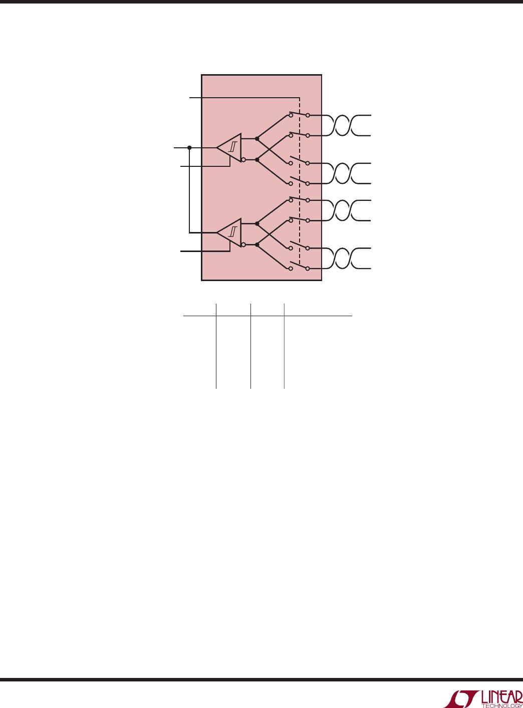
Figure 26. RS485 Receiver with 4-Way Selectable Inputs
2872 F26
H/
F
RA1
RXEN
1
RS485
INTERF
ACE
INPUT1
INPUT2
Y1
Z1
A1
B1
L
TC2872
S3
H/
F
RA2
RXEN
2
INPUT3
INPUT4
Y2
Z2
A2
B2
S1
OUTPUT
S2
S2
1
1
0
0
1
0
S1
0
0
1
1
1
0
SELECTED INPUT
INPUT1
INPUT2
INPUT3
INPUT4
NONE/Hi-Z
INV
ALID
S3
1
0
1
0
X
X
V
CC
= 3V to 5.5V
, V
L
= 1.7V to V
CC
. Logic input pins not shown are tied to a valid logic
state. External components necessary for operation are not shown.
P1-P3
P4-P6
P7-P9
P10-P12
P13-P15
P16-P18
P19-P21
P22-P24
P25-P27
P28-P28
LTC2872IUHF#PBF
Mfr. #:
Buy LTC2872IUHF#PBF
Manufacturer:
Analog Devices Inc.
Description:
RS-232 Interface IC RS232/RS485 Dual Port Multiprotocol Transceiver with Integrated Termination (Shared I/O)
Lifecycle:
New from this manufacturer.
Delivery:
DHL
FedEx
Ups
TNT
EMS
Payment:
T/T
Paypal
Visa
MoneyGram
Western
Union
Products related to this Datasheet
LTC2872IUHF#PBF
LTC2872CUHF#PBF
LTC2872CUHF#TRPBF
LTC2872IUHF#TRPBF