IDT
®
Low Power Clock for Intel Atom
®
-Based Systems 1561C — 08/24/11
9LPRS436C
Low Power Clock for Intel Atom
®
-Based Systems
16
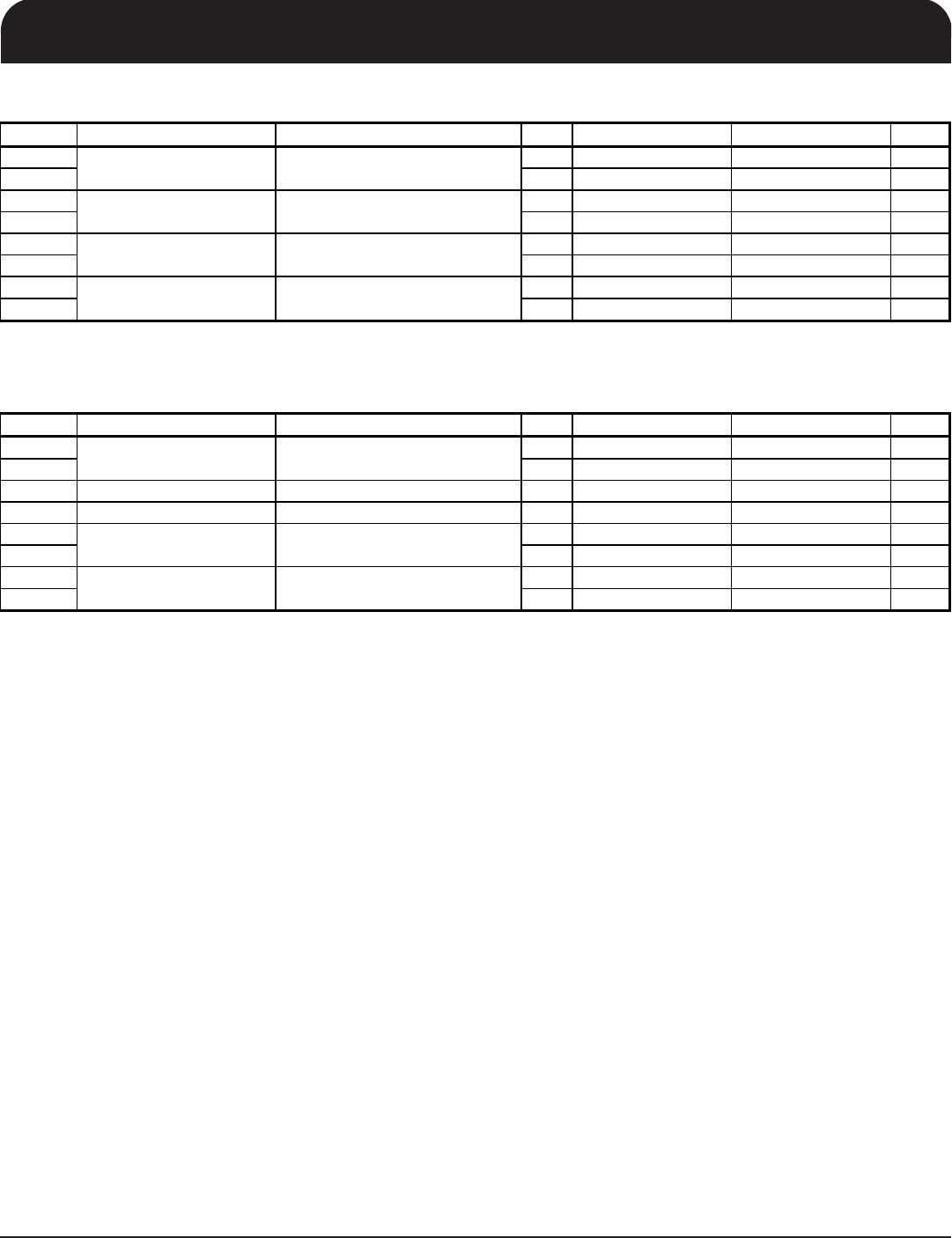
SMBus Table: CPU/SRC/PCI PLL Frequency Control Register
Byte 11 Name Control Function Type 0 1 PWD
Bit 7
N Div2 N Divider Prog bit 2 RW X
Bit 6
N Div1 N Divider Prog bit 1 RW X
Bit 5
M Div5 RW X
Bit 4
M Div4 RW X
Bit 3
M Div3 RW X
Bit 2
M Div2 RW X
Bit 1
M Div1 RW X
Bit 0
M Div0 RW X
SMBus Table: CPU/SRC/PCI PLL Frequency Control Register
Byte 12 Name Control Function Type 0 1 PWD
Bit 7
N Div10 RW X
Bit 6
N Div9 RW X
Bit 5
N Div8 RW X
Bit 4
N Div7 RW X
Bit 3
N Div6 RW X
Bit 2
N Div5 RW X
Bit 1
N Div4 RW X
Bit 0
N Div3 RW X
SMBus Table: CPU/SRC/PCI PLL Frequency Control Register
Byte 13 Name Control Function Type 0 1 PWD
Bit 7
SSP7 RW X
Bit 6
SSP6 RW X
Bit 5
SSP5 RW X
Bit 4
SSP4 RW X
Bit 3
SSP3 RW X
Bit 2
SSP2 RW X
Bit 1
SSP1 RW X
Bit 0
SSP0 RW X
SMBus Table: CPU/SRC/PCI PLL Frequency Control Register
Byte 14 Name Control Function Type 0 1 PWD
Bit 7
SSP15 RW 0
Bit 6
SSP14 RW X
Bit 5
SSP13 RW X
Bit 4
SSP12 RW X
Bit 3
SSP11 RW X
Bit 2
SSP10 RW X
Bit 1
SSP9 RW X
Bit 0
SSP8 RW X
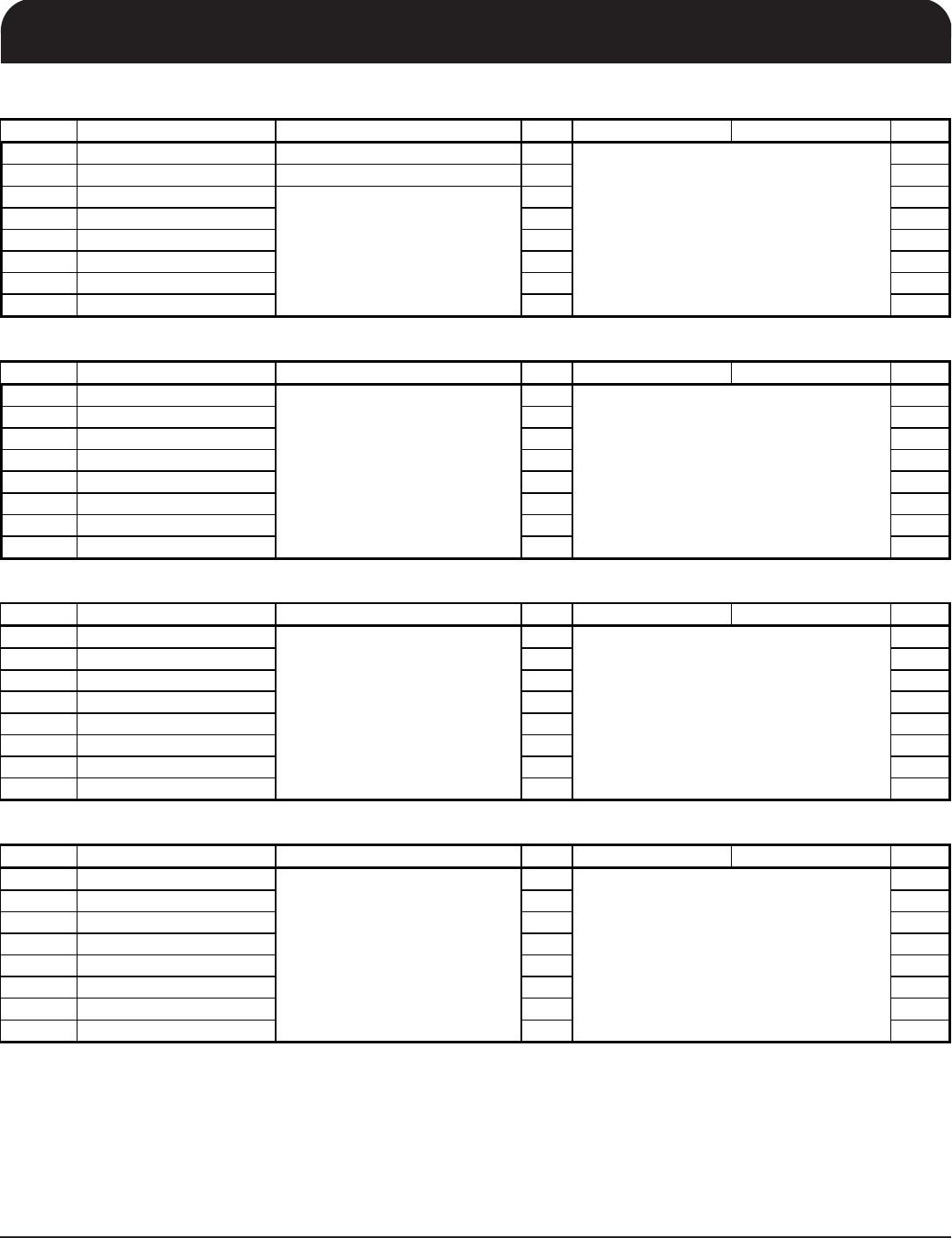
Bytes [15:22] Are reserved
Spread Spectrum Programming
bit(15:8)
Spread Spectrum Programming
bit(7:0)
N Divider Programming Byte12
bit(7:0) and Byte11 bit(7:6)
M Divider Programming
bit (5:0)
These Spread Spectrum bits in Byte 13
and 14 will program the spread percentage
of CPU PLL
These Spread Spectrum bits in Byte 13
and 14 will program the spread percentage
of CPU PLL
The decimal representation of M and N
Divider in Byte 11 and 12 will configure the
CPU PLL VCO frequency. Default at
power up = latch-in or Byte 0 ROM table.
VCO Frequency = 50 x
Ndiv(10:0)/Mdiv(5:0)
The decimal representation of M and N
Divider in Byte 11 and 12 will configure the
CPU PLL VCO frequency. Default at
power up = latch-in or Byte 0 ROM table.
VCO Frequency = 50 x
Ndiv(10:0)/Mdiv(5:0)