LTC1068 Series
6
1068fc
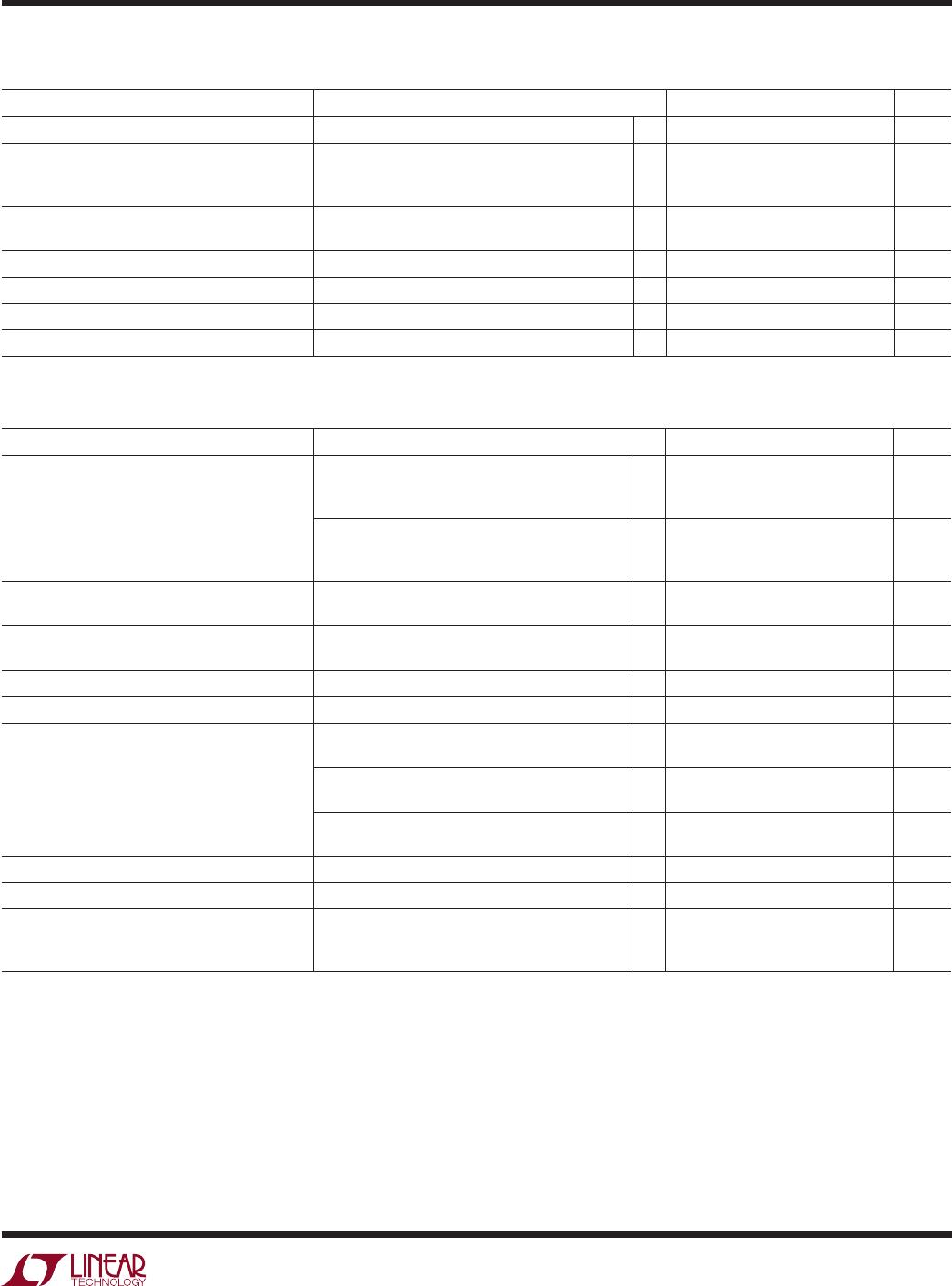
ELECTRICAL CHARACTERISTICS
LTC1068-25 (Internal Op Amps). The l denotes the specifications which
apply over the full operating temperature range, otherwise specifications are at V
S
= ±5V, T
A
= 25°V, unless otherwise noted.
PARAMETER CONDITIONS MIN TYP MAX UNITS
Operating Supply Voltage Range 3.14 ±5.5 V
Voltage Swings V
S
= 3.14V, R
L
= 5k (Note 2)
V
S
= 4.75V, R
L
= 5k (Note 3)
V
S
= ±5V, R
L
= 5k
l
l
l
1.2
2.6
±3.4
1.6
3.4
±4.1
V
P-P
V
P-P
V
Output Short-Circuit Current (Source/Sink) V
S
= ±4.75V
V
S
= ±5V
17/6
20/15
mA
mA
DC Open-Loop Gain R
L
= 5k 85 dB
GBW Product V
S
= ±5V 6 MHz
Slew Rate V
S
= ±5V 10 V/µs
Analog Ground Voltage (Note 4) V
S
= 5V, Voltage at AGND 2.5V ±2% V
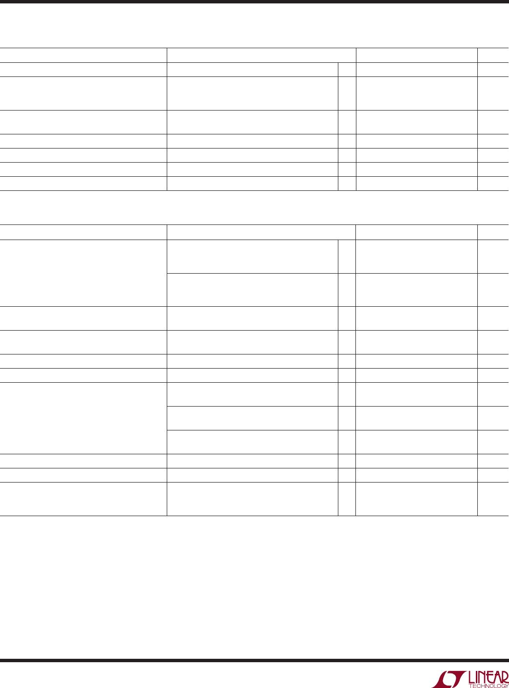
LTC1068-25 (Complete Filter) V
S
= ±5V, T
A
= 25°V, unless otherwise noted.
PARAMETER CONDITIONS MIN TYP MAX UNITS
Clock-to-Center Frequency Ratio
(Note 5) V
S
= 4.75V, f
CLK
= 500kHz, Mode 1 (Note 3),
f
O
= 20kHz, Q = 5, V
IN
= 0.5V
RMS
,
R1 = R3 = 49.9k, R2 = 10k
l
25 ±0.3 25 ±0.8
25 ±0.9
%
%
V
S
= ±5V, f
CLK
= 1MHz, Mode 1,
f
O
= 40kHz, Q = 5, V
IN
= 1V
RMS
,
R1 = R3 = 49.9k, R2 = 10k
l
25 ±0.3 25 ±0.8
25 ±0.9
%
%
Clock-to-Center Frequency Ratio,
Side-to-Side Matching (Note 5)
V
S
= 4.75V, f
CLK
= 500kHz, Q = 5 (Note 3)
V
S
= ±5V, f
CLK
= 1MHz, Q = 5
l
l
±0.25
±0.25
±0.9
±0.9
%
%
Q Accuracy (Note 5) V
S
= 4.75V, f
CLK
= 500kHz, Q = 5 (Note 3)
V
S
= ±5V, f
CLK
= 1MHz, Q = 5
l
l
±1
±1
±3
±3
%
%
f
O
Temperature Coefficient ±1 ppm/°C
Q Temperature Coefficient ±5 ppm/°C
DC Offset Voltage (Note 5)
(See Table 1)
V
S
= ±5V, f
CLK
= 1MHz, V
OS1
(DC Offset of Input Inverter)
l
0 ±15 mV
V
S
= ±5V, f
CLK
= 1MHz, V
OS2
(DC Offset of First Integrator)
l
–2 ±25 mV
V
S
= ±5V, f
CLK
= 1MHz, V
OS3
(DC Offset of Second Integrator)
l
–5 ±40 mV
Clock Feedthrough V
S
= ±5V, f
CLK
= 1MHz 0.25 mV
RMS
Max Clock Frequency (Note 6) V
S
= ±5V, Q ≤ 1.6, Mode 1 5.6 MHz
Power Supply Current V
S
= 3.14V, f
CLK
= 1MHz (Note 2)
V
S
= 4.75V, f
CLK
= 1MHz (Note 3)
V
S
= ±5V, f
CLK
= 1MHz
l
l
l
3.5
6.5
9.5
8
11
15
mA
mA
mA
Note 1: Stresses beyond those listed under Absolute Maximum Ratings
may cause permanent damage to the device. Exposure to any Absolute
Maximum Rating condition for extended periods may affect device
reliability and lifetime.
Note 2: Production testing for single 3.14V supply is achieved by using
the equivalent dual supplies of ±1.57V.
Note 3: Production testing for single 4.75V supply is achieved by
using the equivalent dual supplies of ±2.375V.
Note 4: Pin 7 (AGND) is the internal analog ground of the device. For
single supply applications this pin should be bypassed with a 1µF
capacitor. The biasing voltage of AGND is set with an internal resistive
divider from Pin 8 to Pin 23 (see Block Diagram).
Note 5: Side D is guaranteed by design.
Note 6: See Typical Performance Characteristics.