Description
The A4403 is a buck converter that uses valley current-mode
control. This control scheme allows very short switch on-times
to be achieved, making it ideal for applications that require
high switching frequencies combined with high input voltages
and low output voltages.
Low cost is accomplished through high switching frequencies
of up to 2 MHz, allowing smaller and lower value inductors
and capacitors. In addition, minimal external components are
required through high levels of integration. Optimal drive
circuits are utilized to minimize switching losses.
The switching frequency is maintained constant, as the on-time
is modulated by the input voltage. This feed-forward control
ensures excellent line correction. The on-time is set by an
external resistor pulled-up to the input supply.
When power is initially applied and the device is enabled, a
user-configurable soft-start function occurs to minimize inrush
current and to prevent output overshoot. Internal housekeeping
and bootstrap supplies are provided which only require the
addition of one small ceramic capacitor. A top-off charge pump
is also provide to ensure correct operation at light loads.
Internal diagnostics provide comprehensive protection against
overcurrents, input undervoltages, and overtemperatures.
The device package is a 16-contact, 4 mm × 4 mm, 0.75 mm
nominal overall height QFN, with exposed pad for enhanced
thermal dissipation. It is lead (Pb) free, with 100% matte tin
leadframe plating.
4403-DS, Rev. 2
Features and Benefits
Extremely fast load-transient response with minimal
output voltage delta
Achieves high step-down ratios with on-times < 50 ns
User-configurable on-time, achieving switching
frequencies up to 2 MHz
Minimal external components required
Optimized for low value filter capacitors and inductors
Wide input voltage range: 9 to 46 V
Output Current: 3 A
Low standby current <100 A
Supplied in thermally-enhanced QFN package
Valley Current Mode Control Buck Converter
Applications:
A4403
Package 16-contact QFN (suffix EU):
Printers, scanners
Cable, DSL modems/routers
Network and telecom
Industrial control
Distributed power systems
Set top box
High power LED supply
Battery chargers
GPS / Infotainment
4 mm × 4 mm × 0.75 mm
GND
L
D1
1
6.3 H
LX
FB
VIN
5.0 V
3 A
6.3 V
ISEN
SGND
V
OUT
A 4403
TON
22 nF
R1
100 k
C1
2.2 F
100 V
50 m
SS
DIS
R3
750
R6
3.92 k
R5
C2
47 nF
C5
10 F
C3
6.3 V
10 F
C4
BOOT
V
IN
9 to 46 V
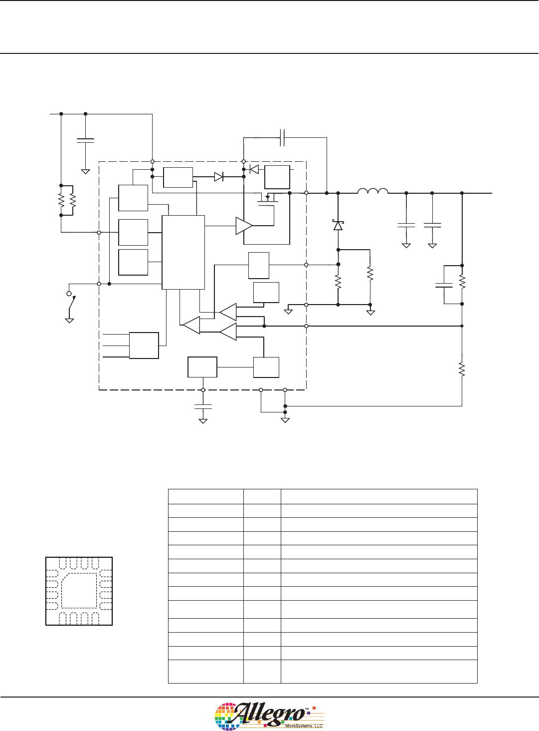
All capacitors are X5R or X7R ceramic
Resistors R3 and R4 should be surface mount, low inductance type, rated at 250 mW at 70°C
Typical Application Diagram
Efficiency versus Output Current
V
IN
= 42 V
60.00
65.00
70.00
75.00
80.00
85.00
90.00
0123
Output Current (A)
Efficiency (%)
5 V
3.3 V