High Voltage
Charge Pump, PLL Synthesizer
Data Sheet
ADF4113HV
Rev. B Document Feedback
Information furnished by Analog Devices is believed to be accurate and reliable. However, no
responsibility is assumed by Analog Devices for its use, nor for any infringements of patents or other
rights of third parties that may result from its use. Specifications subject to change without notice. No
license is granted by implication or otherwise under any patent or patent rights of Analog Devices.
Trademarks and registered trademarks are the property of their respective owners.
One Technology Way, P.O. Box 9106, Norwood, MA 02062-9106, U.S.A.
Tel: 781.329.4700 ©20072012 Analog Devices, Inc. All rights reserved.
Technical Support www.analog.com
FEATURES
High voltage charge pump (15 V)
2.7 V to 5.5 V power supply
200 MHz to 4.0 GHz frequency range
Pin compatible with ADF4110, ADF4111, ADF4112, ADF4113
ADF4106, and ADF4002 synthesizers
Two selectable charge pump currents
Digital lock detect
Power-down mode
Loop filter design possible with ADIsimPLL
APPLICATIONS
Applications using high voltage VCOs
IF/RF local oscillator (LO) generation in base stations
Point-to-point radio LO generation
Clock for analog-to-digital and digital-to-analog converters
Wireless LANs, PMR
Communications test equipment
GENERAL DESCRIPTION
The ADF4113HV is an integer-N frequency synthesizer with a
high voltage charge pump (15 V). The synthesizer is designed
for use with voltage controlled oscillators (VCOs) that have
high tuning voltages (up to 15 V). Active loop filters are often
used to achieve high tuning voltages, but the ADF4113HV
charge pump can drive a high voltage VCO directly with a
passive-loop filter. The ADF4113HV can be used to implement
local oscillators in the upconversion and downconversion
sections of wireless receivers and transmitters. It consists of a
low noise digital phase frequency detector (PFD), a precision
high voltage charge pump, a programmable reference divider,
programmable A and B counters, and a dual-modulus prescaler
(P/P + 1).
A simple 3-wire interface controls all of the on-chip registers.
The devices operate with a power supply ranging from 2.7 V to
5.5 V and can be powered down when not in use.
FUNCTIONAL BLOCK DIAGRAM
C
LK
DATA
LE
MU
XOUT
ADF4113
HV
C
P
CE AGN
D DGND
CPGND
22
14
REFERENCE
M3 M2
M1
6
HIGH Z
N = BP +
A
CHARGE
PUMP
CURREN
T
SETT
IN
G
MUX
R
SE
T
V
P
PHASE
F
REQ
UENC
Y
DETECTOR
LOCK
D
ETEC
T
AV
DD
SD
OUT
24-
BIT
INPUT REGISTER
DV
DD
A
V
DD
19
13
SD
OU
T
REF
IN
14-
BIT
R CO
UNT
ER
R
F
IN
A
RF
IN
B
R COUNTER
LA
TCH
F
UNCTIO
N
LATCH
A, B
COUNTER
LATC
H
FROM
F
UNCTION
LATC
H
13-BI
T
B
COUNTER
6-BI
T
A COUNTER
P
RESCALER
P/P + 1
06223-001
LOAD
LOAD
Figure 1.
ADF4113HV* PRODUCT PAGE QUICK LINKS
Last Content Update: 02/23/2017
COMPARABLE PARTS
View a parametric search of comparable parts.
EVALUATION KITS
ADF4113HV Evaluation Board
DOCUMENTATION
Application Notes
AN-30: Ask the Applications Engineer - PLL Synthesizers
Data Sheet
ADF4113HV: High Voltage Charge Pump, PLL Synthesizer
Data Sheet
User Guides
UG-165: Evaluation Board for Integer-N PLL Frequency
Synthesizer
UG-476: PLL Software Installation Guide
TOOLS AND SIMULATIONS
ADIsimPLL™
ADIsimRF
REFERENCE MATERIALS
Product Selection Guide
RF Source Booklet
DESIGN RESOURCES
ADF4113HV Material Declaration
PCN-PDN Information
Quality And Reliability
Symbols and Footprints
DISCUSSIONS
View all ADF4113HV EngineerZone Discussions.
SAMPLE AND BUY
Visit the product page to see pricing options.
TECHNICAL SUPPORT
Submit a technical question or find your regional support
number.
DOCUMENT FEEDBACK
Submit feedback for this data sheet.
This page is dynamically generated by Analog Devices, Inc., and inserted into this data sheet. A dynamic change to the content on this page will not
trigger a change to either the revision number or the content of the product data sheet. This dynamic page may be frequently modified.
ADF4113HV Data Sheet
Rev. B | Page 2 of 20
TABLE OF CONTENTS
Features .............................................................................................. 1
Applications ....................................................................................... 1
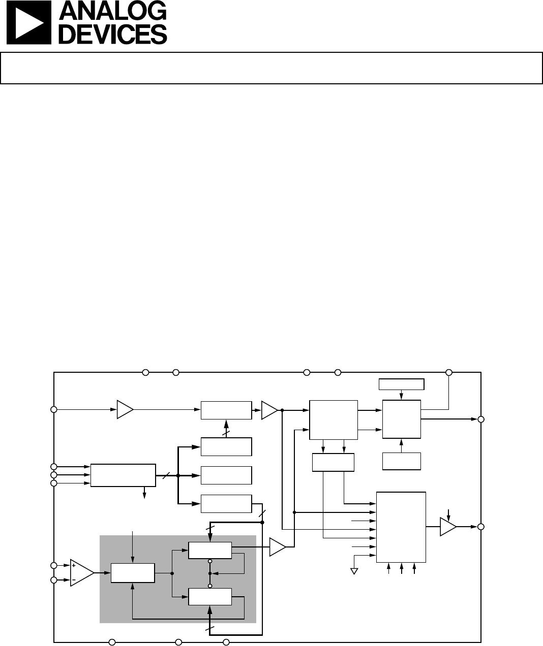
Functional Block Diagram .............................................................. 1
Revision History ............................................................................... 2
Specifications ..................................................................................... 3
Timing Characteristics ................................................................ 4
Absolute Maximum Ratings ............................................................ 5
Transistor Count ........................................................................... 5
Thermal Resistance ...................................................................... 5
ESD Caution .................................................................................. 5
Pin Configurations and Function Descriptions ........................... 6
Typical Performance Characteristics ............................................. 7
Circuit Description ........................................................................... 9
Reference Input Section ............................................................... 9
RF Input Stage ............................................................................... 9
Prescaler (P/P + 1) ........................................................................9
A and B Counters ..........................................................................9
R Counter .......................................................................................9
Phase Frequency Detector (PFD) and Charge Pump ............ 10
Muxout and Lock Detect ........................................................... 10
Input Shift Register .................................................................... 10
Function Latch ............................................................................ 13
Applications ..................................................................................... 15
Using a Digitial-to-Analog Converter to Drive
the R
SET
Pin .................................................................................. 15
Interfacing ................................................................................... 15
PCB Design Guidelines for Chip Scale Package .................... 16
Outline Dimensions ....................................................................... 17
Ordering Guide .......................................................................... 17
REVISION HISTORY
10/12Rev. A to Rev. B
Changed CP-20-1 Package to CP-20-6 Package ............. Universal
Changes to Table 3 and Table 4 ....................................................... 5
Added EPAD Notation..................................................................... 6
Updated Outline Dimensions ....................................................... 17
Changes to Ordering Guide .......................................................... 17
9/08—Rev. 0 to Rev. A
Changes to Figure 22 ...................................................................... 13
1/07—Revision 0: Initial Version

ADF4113HVBRUZ-RL7

Mfr. #:
Manufacturer:
Analog Devices Inc.
Description:
Phase Locked Loops - PLL High VTG Charge Pump
Lifecycle:
New from this manufacturer.
Delivery:
DHL FedEx Ups TNT EMS
Payment:
T/T Paypal Visa MoneyGram Western Union