NB3H63143G
www.onsemi.com
11
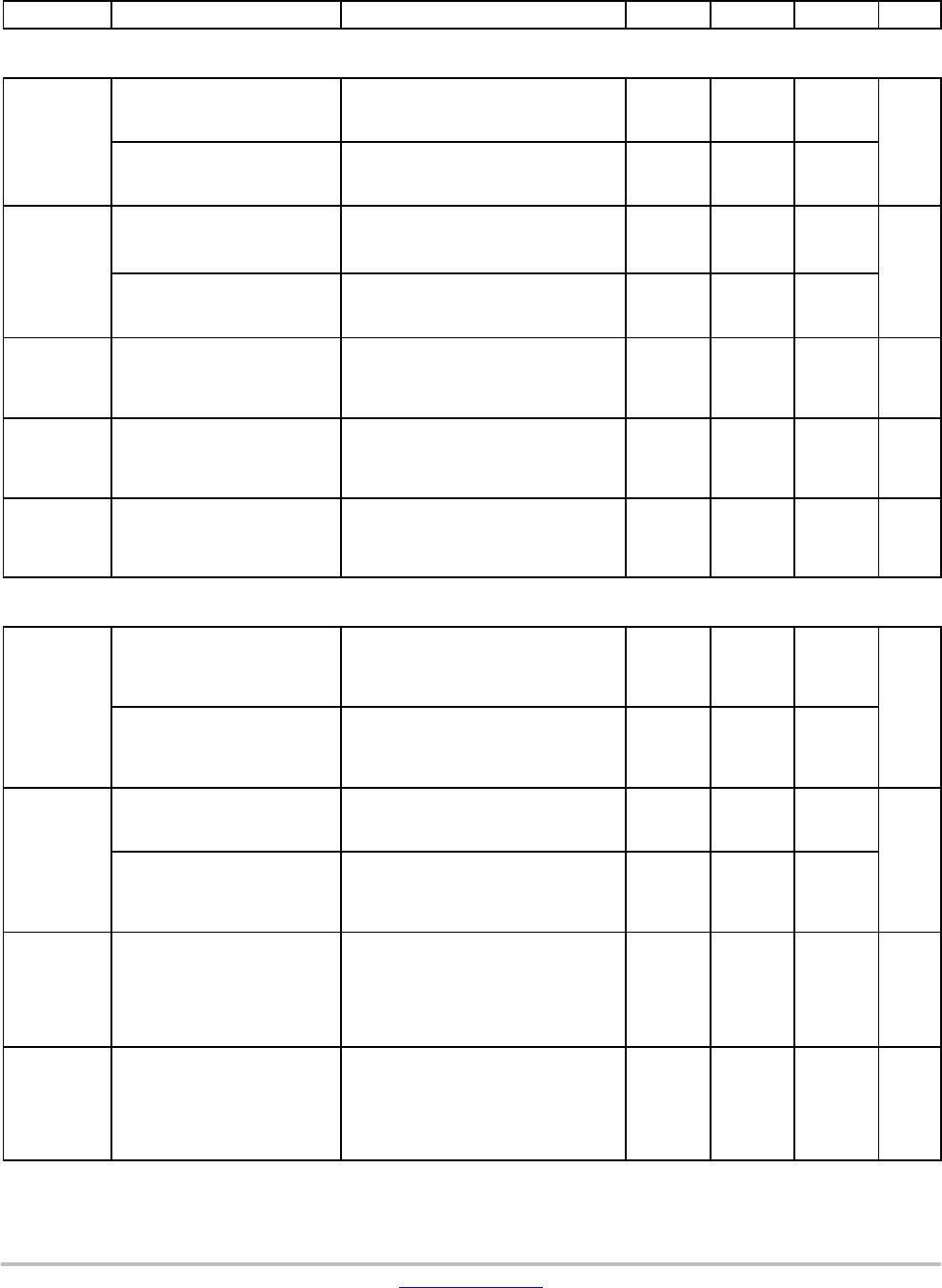
DC ELECTRICAL CHARACTERISTICS (continued)
(V
DD
= 3.3 V ±10%, 2.5 V ±10%, VDDO[2:0] = 3.3 V ± 10%, 2.5 V ± 10%, 1.8 V ± 0.1 V; GND = 0 V, T
A
= −40°C to 85°C, Note 19)
Symbol UnitMaxTypMinConditionParameter
CML OUTPUTS (Notes 17 and 18)
I
DDO_CML
f
out
= 100 MHz
f
out
= 200 MHz
5.0 mA
Product parametric performance is indicated in the Electrical Characteristics for the listed test conditions, unless otherwise noted. Product
performance may not be indicated by the Electrical Characteristics if operated under different conditions.
NOTE: Device will meet the specifications after thermal equilibrium has been established when mounted in a test socket or printed circuit
board with maintained transverse airflow greater than 500 lfpm.
7. Measurement taken with single ended clock outputs terminated with test load capacitance of 5 pF and 15 pF and differential clock
terminated with test load of 2 pF. See Figures 6, 7 and 12. Specifications for LVTTL are valid for VDD and VDDO 3.3 V only.
8. Measurement taken with outputs terminated with RS = 0 W, RL = 50 W, with test load capacitance of 2 pF. See Figure 8. Guaranteed by
characterization.
9. Measurement taken from single ended waveform.
10.Measured at crossing point where the instantaneous voltage value of the rising edge of CLKx+ equals the falling edge of CLKx−.
11. Refers to the total variation from the lowest crossing point to the highest, regardless of which edge is crossing. Refers to all crossing points
for this measurement.
12.Defined as the total variation of all crossing voltage of rising CLKx+ and falling CLKx−. This is maximum allowed variance in the VCROSS
for any particular system.
13.LVDS outputs require 100 W receiver termination resistor between differential pair. See Figure 9.
14.VOHmax = VOSmax + 1/2 VODmax.
15.VOLmax = VOSmin − 1/2 VODmax.
16.LVPECL outputs loaded with 50 W to VDDO1 − 2.0 V for proper operation.
17.Output parameters vary 1:1 with VDDO1.
18.CML outputs loaded with 50 W to VDDO1 for proper operation.
19.Parameter guaranteed by design verification not tested in production.
AC ELECTRICAL CHARACTERISTICS (V
DD
= 3.3 V ±10%, 2.5 V ±10%, VDDO[2:0] = 3.3 V ± 10%, 2.5 V ± 10%, 1.8 V
± 0.1 V; V
DDO
≤ V
DD
, GND = 0 V, T
A
= −40°C to 85°C, Notes 19, 20, 23, 24 and 25)
Symbol
Parameter Condition Min Typ Max Unit
f
out
Single Ended Output
Frequency
0.008 200 MHz
f
MOD
Spread Spectrum Modulation
Rate
fclkin ≥ 6.75 MHz 30 130 kHz
SS Percent Spread Spectrum
(deviation from nominal
frequency)
Down Spread 0 −4 %
Center Spread 0 ±3 %
SSstep Percent Spread Spectrum
Change Step Size
Down Spread Step Size 0.25 %
Center Spread Step Size 0.125 %
SSC
RED
Spectral Reduction,
3
rd harmonic
@SS = −0.5%, f
out
= 100 MHz,
fclkin = 25 MHz Crystal, RES BW at
30 kHz, All Output Types
−10 dB
t
PU
Stabilization Time from
Power−up
V
DD
= 3.3 V, 2.5 V with Frequency
Modulation ON
3.0 ms
t
PD
Stabilization Time from
Power Down
Time from falling edge on PD pin to
Tri−stated Outputs (Asynchronous)
3.0 ms
t
SEL
Stabilization Time from
Change of Configuration
With Frequency Modulation ON 3.0 ms
t
OE1
Output Enable Time Time from rising edge on OE pin to
valid clock outputs (asynchronous)
2/f
out
(MHz)
ms
t
OE2
Output Disable Time Time from falling edge on OE pin to
valid clock outputs (asynchronous)
2/f
out
(MHz)
ms
Eppm Synthesis Error Configuration Dependent 0 ppm