CS3301
DS595F3 11
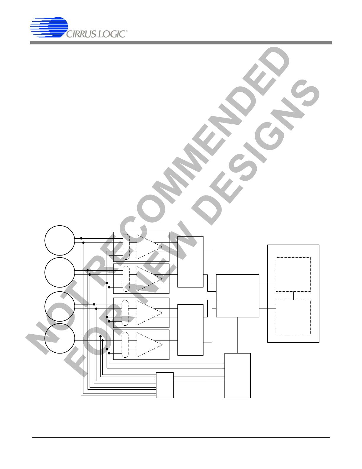
2.1.3 Differential Signals
Analog signals into and out of the CS3301 are dif-
ferential, consisting of two halves with equal but
opposite magnitude varying about a common mode
voltage.
A full scale 5 Vpp differential signal centered on a
-0.15 V common mode can have:
SIG+ = -0.15 V + 1.25 V = 1.1 V
SIG- = -0.15 V - 1.25 V = -1.4 V
SIG+ is +2.5 V relative to SIG-
For the reverse case:
SIG+ = -0.15 V - 1.25 V = -1.4 V
SIG- = -0.15 V + 1.25 V = 1.1 V
SIG+ is -2.5 V relative to SIG-
The total swing for SIG+ relative to SIG- is
(+2.5 V) - (-2.5 V) = 5 V
pp
. A similar calculation
can be done for SIG- relative to SIG+. Note that a
5V
pp
differential signal centered on a -0.15 V
common mode voltage never exceeds 1.1 V and
never drops below -1.4 V on either half of the sig-
nal.
By definition, differential voltages are to be mea-
sured with respect to the opposite half, not relative
to ground. A multimeter differentially measuring
between SIG+ and SIG- in the above example
would properly read 1.767 V
rms
, or 5 V
pp
.
2.2 Digital Signals
2.2.1 Clock Input
The clock signal is used by the chopper-
stabilization circuitry of the amplifier analog in-
puts. The CLK pin can be driven by an external
clock source for synchronous operation, or CLK
can be grounded to run from its own internally gen-
erated clock signal. The CLK pin is connected to a
clock detect circuit which will disable the internal
clock and use an external clock if one is supplied.
If the internal clock signal is to be used, the CLK
pin should be connected to DGND.
2.2.2 Gain Selection
The CS3301 supports gain ranges of x1, x2, x4, x8,
x16, x32, and x64. They are selected using the
GAIN0, GAIN1, and GAIN2 pins as shown in
Table 1 on page 8.
2.2.3 Mux Selection
The analog inputs to the amplifier are multiplexed,
with external signals applied to the INA+, INA- or
INB+, INB- pins. An internal termination is also
available for noise tests. Input mux selection is
made using the MUX0 and MUX1 pins as shown in
Table 1 on page 8.
Although a mux selection is provided to enable the
INA and INB switches simultaneously, significant
current should not be driven through them in this
mode. The CS3301 mux switches will maintain
good linearity only with minimal signal currents.
2.2.4 Low Power Selection
For applications where power is critical, a low-
power mode can be selected. This mode reduces
amplifier power consumption at the expense of
slightly degraded performance. Low power mode
is selected using the LPWR pin, which is active
high.
2.2.5 Power Down Selection
A power-down mode is available to shut down the
amplifier when not in use. When enabled, all inter-
nal circuitry is disabled, the analog inputs and out-
puts go high-impedance, and the device enters a
micro-power state. Power down mode is selected
using the PWDN pin, which is active high.
2.3 Power Supplies
2.3.1 Analog Power Supplies
The analog power pins of the CS3301 are to be sup-
plied with a total of 5 V between VA+ and VA-.
This voltage is typically from a bipolar
±2.5 V
power supply. When using bipolar power supplies,
the analog signal common mode voltage should be
biased to 0 V. The analog power supplies are rec-